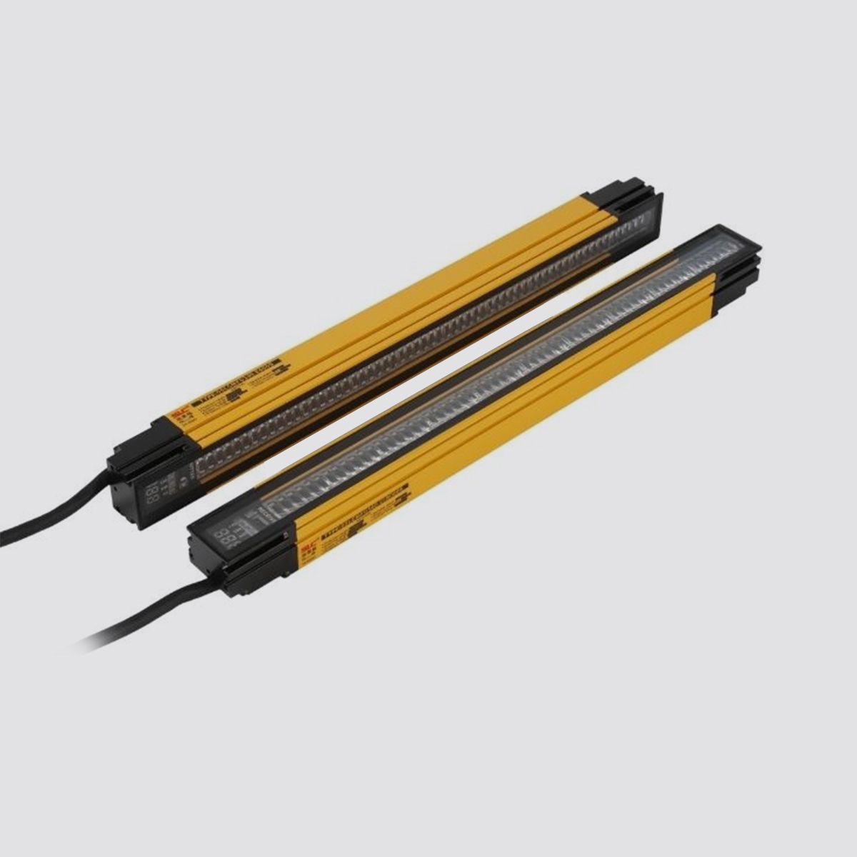
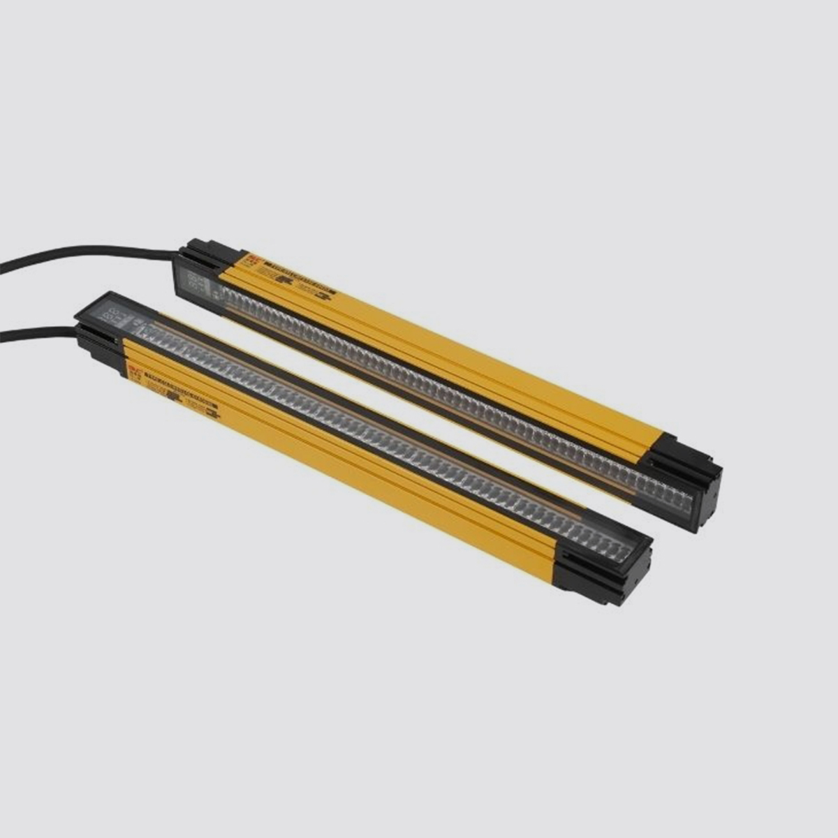
Product Detail
Features
▶Three scanning methods:
Straight sweep
one side scan
bilateral scan
▶Up to 20 measurement modes:
FBB, LBB, TBB, MBB
FBM, LBM, TBM
OD, ID
CBB, CBM
CFBB, CLBB
O1FBB, O1LBB, O2FBB, O2LBB, O3FBB, O3LBB TRN
▶Three output methods:
2 independent level outputs
2 independent analog outputs
Standard Modbus 485-RTU serial output
5mm minimum detection target or 2.5mm edge
resolution, depending on scanning method
▶The range of the beam distance is 400mm—4000mm, and the beam interval is 5mm.
▶3-digit digital tube and multiple LED lights are used to indicate the working status
▶It is equipped with PC-side host computer software, which can perform advanced configuration and work monitoring of the grating
▶Supporting the Android system APP, the grating can be connected to the grating through wireless infrared communication
Configure
▶A remote configuration line to configure some simp
le functions: scan mode
Block settings
Alignment calibration
Gain setting
Digital tube display direction
Infrared communication on/off
Technical parameter
Electrical parameters |
Supply voltage | 24VDC±15% |
Maximum power | 10W (without load |
Response time | 24VDC±15% |
OSSD dual output | 10W (without load 20ms |
output feedback | 2 channels of PNP output; each channel drive load capacity 300mA external relay status feedback |
Shell protection class | IP65 |
Shell protection class | 0~55°C |
Storage temperature | -20~55°C |
Relative humidity | 15%~95% |
Optical parameters |
Detection height | 455mm/52*50mm (section size of shell) |
Detection distance | 10m (use with vertical reflector) |
Number of optical axes | 24~480 |
Optical axis spacing | 460mm |
Effective aperture EAA | ±2.5. @3m |
wavelength | 940nm |
Anti-ambient light interference | >10,000Lux |
synchronicity | Optical synchronization |
1. System composition
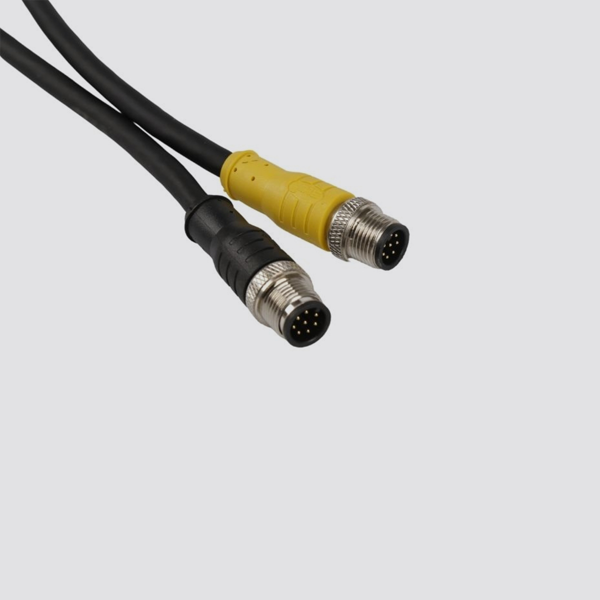
XAORI-LCMF05 series grating consists of transmitter and receiver. Beam synchronization adopts line synchronization method. The power supplies of the transmitter and receiver need to share the ground. The measurement results are output from the receiver, with two level outputs, two analog outputs, and a set of serial data outputs. Digital measurement results are accessed via serial communication. Simple settings can be done through the remote setting line (pink) or Android APP, and advanced settings and detailed data can be done through the PC on the computer.
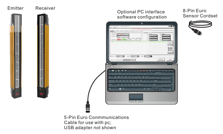
Figure 1.1 Schematic diagram of LCMF05 series measuring grating system
2. Scan method
Rasters have three scanning methods to choose from:
Straight sweep
one side scan
Bilateral sweep (steps can be selected from 1, 2, 4, 8, 16, 32)
The response time of the grating depends on the number of grating channels and the grating scanning method, see Table 2 for details.
Straight sweep
Straight scan is the default scan method for raster. In this mode, all beam channels of the grating are scanned sequentially, from the first beam of the grating to the last beam. This scanning method can provide the smallest inspection objects with an edge resolution of 5mm.
When low gain is selected, the minimum object detection size is 5mm.
When high gain is selected, the minimum object detection size is 10mm.
Single side scan
Single-sided scanning is used to measure the height of a single object. This scanning method is often used for box height measurements. In this mode, the raster always scans the first beam channel (the lowest channel, near the nixie tube). When the first beam channel is blocked, the grating performs a dichotomous scan to find the last blocked beam. Taking 72 channels as an example, the execution steps of single-side scanning are shown in Figure 1.2.

Figure 1.2 Take 72 channels as an example, single side scan scan 01→72→36→18→27→22→24→25
Single-sided scanning can only be used for single, continuous object detection that can block the first beam path. Because the grating only scans the other channels when the first beam channel is blocked. For discontinuous objects, the scan result is invalid. Single side scan is fixed to work in high gain mode. Setting low gain has no effect on it. The minimum detection object size of single-side scanning is 10mm, and the edge resolution is 2.5mm.
Bilateral scan
Bilateral scanning is used to detect both edges of an object. For example, the dimensions used to determine the width of a box. When bilateral scanning is selected, a step needs to be determined: 1, 2, 4, 8, 16 or 32. The grating will scan by skipping some beams depending on the step size. Taking 72 channels as an example, the execution steps of bilateral scanning are shown in Figure 1.3。

Figure 1.3 Taking 72 channels as an example, the scanning sequence of bilateral scanning beams: 01→05→09→13→17→15→14→21→25→29→33→37→41→39→40→43→47→51→55→59→63→67→71→72
Similar to single-sided scanning, bilateral scanning also has some usage limitations: the detection object is a continuous opaque solid; the minimum detection object size is larger than the bilateral scanning step.
Bilateral scanning can detect up to 3 objects.
Double-scan is fixed to work in high gain mode. Setting low gain has no effect on it.
The minimum detected object size for bilateral scanning is related to the scanning step, and the edge resolution is 2.5mm.
Scan method | Straight sweep | one side scan | bilateral scan |
low gain | high gain | Scan step |
1 | 2 | 4 | 8 | 16
| 32 |
Minimum detection object | 5mm | 10mm | 10mm | 10mm | 20mm | 30mm | 50mm | 90mm | 170mm |
edge resolution | 5mm | 5mm | 2.5mm | 2.5mm | 2.5mm | 2.5mm | 2.5mm | 2.5mm | 2.5mm |
Table 1.1 Effect of scanning method and stepping on minimum object detection size and edge resolution
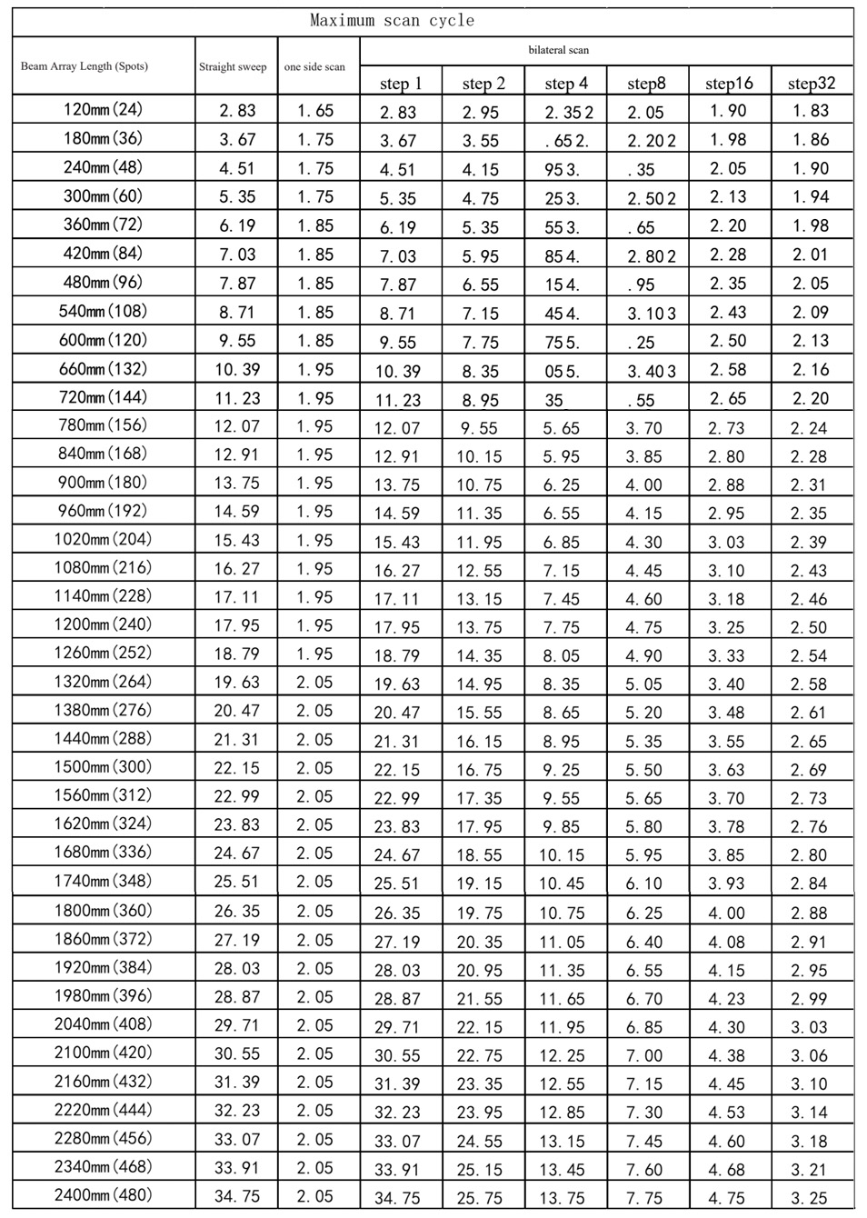
Table 1.2 The maximum scan period of direct scan, single side scan and double side scan
3. Gain Configuration
The raster provides two gain configuration options for direct scanning: high gain and low gain. The gain options can be configured through the computer host computer, Android APP, and the remote setting line (pink).
High gain is suitable for detecting opaque objects, and objects 10mm or larger in harsher environments. High gain is always applied in single side scan or double side scan. The high gain option is the smallest threshold for occlusion determination, providing reliable object perception.
Low gain is used to detect translucent objects or objects as small as 5mm (direct scan). Low gain provides 9 different levels of occlusion judgment threshold lines, from 10%-50%, every 5%. The user selects the appropriate low gain according to the actual situation
Gain selection | low gain | high gain |
Scan method | Straight sweep | one side scan | bilateral scan | Straight sweep | one side scan | bilateral scan |
Minimum detection object | 5mm | - | - | 10mm | 10mm | related to stepping |
edge resolution | 5mm | - | - | 5mm | 2.5mm | Single edge 2.5mm/overall 5mm |
Table 1.3 Effect of gain on minimum detected object and edge resolution
4. Alignment Calibration
The purpose of grating alignment calibration is to adjust the luminous power level of the transmitter to maximize sensor performance. Perform the calibration process at installation. When the transmitter or receiver is moved, the calibration process must be performed again.
During calibration, the receiver takes measurements for each beam channel and adjusts the gain of each channel if necessary, and stores it in non-volatile memory.
The calibration process can be carried out through the host computer on the computer, the Android app or the remote setting line (pink).
5. Shield
During the operation of the grating, if one or more beam channels are fixedly blocked by a machine or device, these beam channels can be blocked. Shielded beam channels, the raster will ignore the state of these channels during scanning and measurement calculations.
The shielding setting can be done through the PC on the computer, the Android APP or the remote setting line (pink).
For quantitative measurements (eg TBB, TBM, CBB, CBM), shielded or unshielded channels affect the analog output. When calculating the analog output size, the total needs to be subtracted from the number of shielded channels.
6. Measurement data
The grating has 20 kinds of measurement data, which can be divided into beam position, beam number, or edge count. All measurement data can be read out through the serial interface, please refer to the Modbus RTU register description for details. Not all measurement data are valid, and are related to the current scanning method, see Table 1.4 for details. The first 14 kinds of measurement data can be allocated to public measurement 1 and public measurement 2, but invalid measurement data cannot be allocated for use. Users need to configure the scan method and public measurement 1/2 configuration correctly, otherwise they will be configured. fail.
Measurement type | Paraphrase | Scan Method Restrictions | Remark |
FBB | First Beam Blocked | The position of the first blocked beam | Straight Scan/Single Side Scan/bilateral scan | Beam Position Type |
FBM | First Beam Made | The position of the first blocked beam | Straight sweep |
LBB | Last Beam Blocked | The position of the last blocked beam | Straight Scan/Single Side Scan/bilateral scan |
LBM | Last Beam Made | The position of the last guided beam | Straight sweep |
MBB | Middle Beam Blocked | The middle position of the first and last occluded beams | Straight Scan/Single Side Scan/bilateral scan |
TBB | Total Beams Blocked | Total number of blocked beams | Straight Scan/Single Side Scan/bilateral scan | Beam quantity type |
TBM | Total Beams Made | Total number of guided beams | Straight sweep |
CBB | Contiguous Beams Blocked | Maximum number of continuously blocked beams | Straight Scan/Single Side Scan/bilateral scan |
CBM | Contiguous Beams Made | Maximum number of continuous on-beams | Straight sweep |
TRN | Transitions | Number of edges, conduction to blocking or blocking to conduction, regarded as an edge | Straight Scan/Single Side Scan/Bilateral Scan | other types |
OD | Outside Dimension | Number of beams between the first occluded beam and the last occluded beam | Straight Scan/Bilateral Scan |
ID | Inside Dimension | Number of guided beams between the first blocked beam and the last blocked beam | Straight Scan/Bilateral Scan |
CFBB | Contiguous First Beam Blocked | The position of the first occlusion beam of the maximum continuous occlusion beam | Straight Scan/Single Side Scan/Bilateral Scan |
CLBB | Contiguous Last Beam Blocked | The position of the last occluded beam of the maximum continuous occlusion beam | Straight Scan/ Single Side Scan/ Bilateral Scan |
01FBB | Object 1 First Beam Blocked | The position of the first occluded beam of object 1 | Straight Scan/Single Side Scan/Bilateral Scan |
01LBB | Object 1 Last Beam Blocked | The position of the last occluded beam of object 1 | Straight Scan/Single Side Scan/Bilateral Scan |
02FBB | Object 2 First Beam Blocked | The position of the first occluded beam of object 2 | Straight Scan/Bilateral Scan |
02LBB | Object 2 Last Beam Blocked | The position of the last occluded beam of object 2 | Straight Scan/Bilateral Scan |
03FBB | Object 3 First Beam Blocked | The position of the first occluded beam of object 3 | Straight Scan/Bilateral Scan |
03LBB | Object 3 Last Beam Blocked | The position of the last occluded beam of object 3 | Straight Scan/Bilateral Scan |
Table 1.4 Measurement Types
Note: Only the FBB and LBB of 3 objects can be recorded at most. If there are more than 3 objects, take the FBB and LBB of the first 3 objects,
And use this to calculate CFBB and CLBB

Figure 1.4 Example of measurement data
7. Public measurement
There are many measurement data, and two kinds of measurement data need to be selected as the output reference of the two-channel discrete quantity and the two-channel analog quantity, which are divided into public measurement 1 and public measurement 2. The public measurement data source can be selected from the first 14 measurement data in Table 4. As mentioned in 1.6, under different scanning methods, not all 14 measurement data can be selected as public measurement. The relationship between public measurement data sources and scanning methods is shown in Table 1.5.
scanning method | Publishing measurement data sources |
Straight sweep | FBB、LBB、TBB、TRN、CBB、FBM、LBM、TBM、CBM、MBB、OD、ID、CFBB、CLBB FBB、LBB、TBB、TRN、CBB、MBB、 |
one side scan | CFBB、CLBB |
bilateral scan | FBB、LBB、TBB、TRN、CBB、MBB、OD、ID、CFBB、CLBB |
Table 1.5 Relationship between public measurement data sources and scanning methods B
8. Remote (Teach) setting line
The receiver pink wire (remote setup) is used to simulate a key press. By simulating the action of the key, you can set the common functions of the grating.
Connect a normally open switch between the pink wire and the ground, or send a low pulse through the PLC output port to control it according to Table 5. Low level: 0V-2V; High level: 10V-30V.
The remote setup line has 4 functions: disable (default), remote setup, alignment calibration, gated mode. Select one of the functions through the upper computer software setting or serial communication.
Remote settings
0.05s <= T <= 0.8s. Enter any setting state, if there is no next Teach line action for more than 60s, it will exit the setting state and restore the original parameters. Low level: 0V-2V; High level: 10V-30V.
9. Analog output
There are two analog outputs, which can independently output voltage (0-10V) or current (4-20mA). The two outputs are bound to public measurement 1 and public measurement 2 respectively. When the selected public measurement involves the beam number type, the output of the analog distribution is proportional to the number of beams (unshielded channels) scanned. When the selected public measurement involves the type of beam position, the output of the analog distribution is proportional to the total number of beams of the grating. Beam Quantity Type Measurement Mode: TBB, TBM, CBB, CBM. For more configuration options, refer to Section 4.10.
10. Discrete output
There are two discrete outputs, which can output N-type or P-type signals independently. Discrete output 1 is bound to public measurement 1. In addition to public measurement 2, discrete output 2 can also be selected to indicate the working health of the grating. For more configuration options, refer to Section 4.10.
11. Serial communication
At that time, when using a computer host computer, the computer interface communicated with the grating through Modbus RTU-485. After the host computer selects the correct serial port number, communication address (factory address 0x41), and baud rate (factory baud rate 19200bps), it can exchange data with the grating, including grating parameter configuration, grating measurement data reading, etc.
12. IrDA communication
The grating receiver has a standard IrDA communication interface. After connecting a dedicated converter to the USB port of the mobile phone port, it can communicate with the grating wirelessly through the APP to set the working parameters of the grating.
13. Outline and installation dimensions (mm)

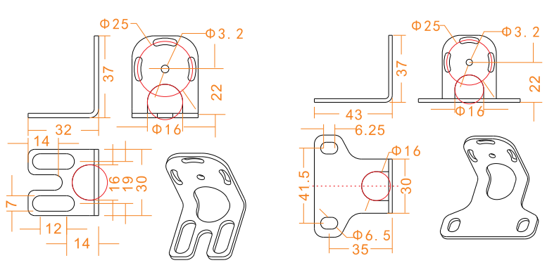
14. Installation steps
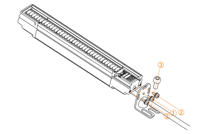
Installation steps of the mounting brackets at both ends:
①Fix the middle hole of the mounting bracket at both ends with the middle hole of the grating end cover with M3 combination screws to ensure that the bracket can be rotated;
②Use M3 combination screws to fix the holes on both sides of the mounting bracket at both ends and the holes on both sides of the grating end cover;
③Fix the grating to the device installation position with M6 screws.
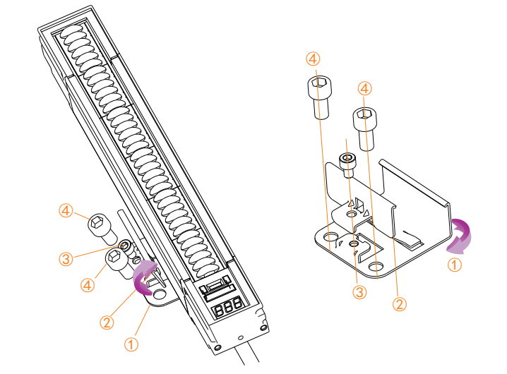
Back Mounting Bracket Installation Steps:
① Fasten the bottom plate of the back bracket to the installation slot on one of the two sides of the grating;
② Buckle the back bracket pressure plate into the installation slot on the other side of the grating to ensure that the middle hole is aligned with the screw hole of the bottom plate;
③Use M4×6 screws to lock the bottom plate of the bracket and the pressure plate to ensure that the two hooks are all buckled into the installation grooves on both sides of the grating;
④Use M6 screws to fix the grating to the installation position of the equipment.
15. Wrongly installing apps

16. Install the app correctly
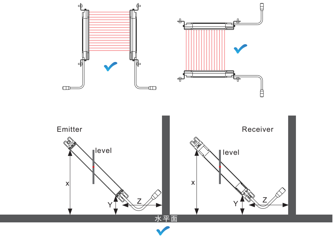
When installed at an angle, it is necessary to ensure that the values in the above figure are only the same in the same position for receiving and
transmitting: transmitting X = receiving X
transmit Y = receive Y
transmit Z = receive Z
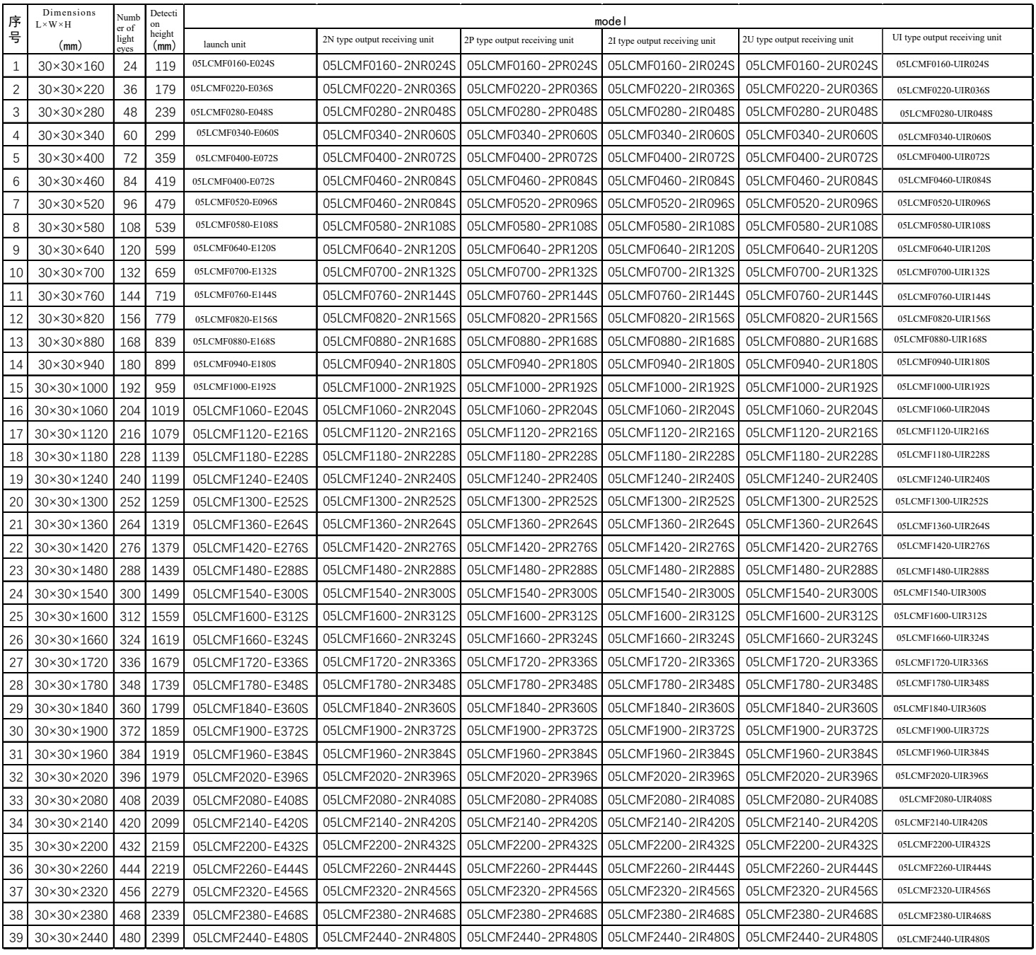
17. Grating specifications and selection
 +86-0755-29898410 +86-0755-29898460
  ron@xaori.net


