Product Detail
Product overview
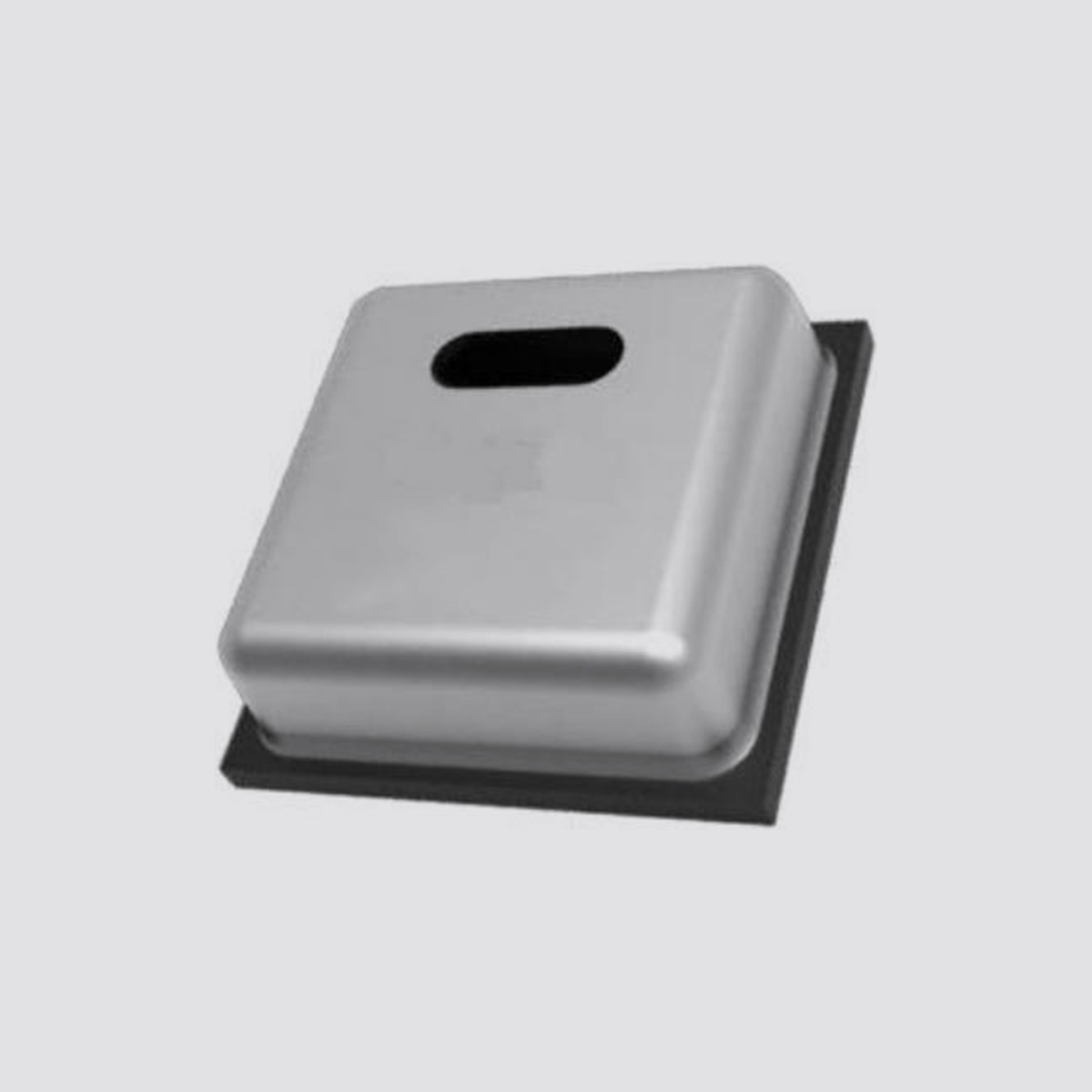
The XRTH22 temperature and humidity sensor is embedded in a double-row flat leadless SMD package suitable for reflow soldering. The temperature and humidity signals can be read out at different pins, with a bottom surface of 3.0×3.0 mm and a height of 1.0mm. The sensor outputs a calibrated digital signal in standard I2C format.
XRTH22 series temperature and humidity sensor, which adopts transistor Vbe temperature characteristic to realize high-precision temperature detection and changes of dielectric constant after moisture absorption to realize environmental humidity detection, is a single-chip solution combined with the latest integrated circuit signal processing technology. It has the advantages of small size, low power consumption, high reliability and good compatibility.
Product features
■High precision, ±2.0% RH and 0.3℃
■Wide supply voltage range, from 2.0 V to 5.5v.
■SMD package, suitable for reflow soldering.
■Quick response and strong anti-interference ability.
■Excellent long-term stability under high humidity conditions
Application scenario
Household appliances: household appliances, humidity control, HVAC, dehumidifier, intelligent thermostat, room monitor; Industry: automobile, test and inspection equipment, automatic control; Other fields: data recorder, weather station, medical treatment and other related temperature and humidity detection and control.
Sensor performance
relative humidity
Table 1 Humidity characteristic table
parameter | condition | smallest | typical | maximum | unit |
Resolution | typical |
| 0.01 |
| %RH |
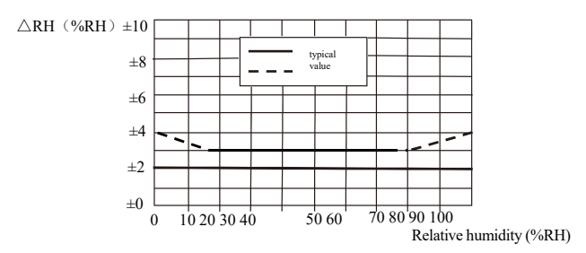
Accuracy error 1 | typical |
| ±2.0 |
| %RH |
maximum | See figure 2. |
| %RH |
repeatability |
|
| ±0.1 |
| %RH |
sluggish |
|
| ±1.0 |
| %RH |
non-linear |
|
| <0.1 |
| %RH |
Response time 2 | t63% |
| eight |
| s |
working range | extended3 | 0 |
| 100 | %RH |
Long time drift 4 | normal |
| <0.5 |
| %RH/yr |
Figure 1 Maximum error of relative humidity at 25 C
temperature
Table 2 Temperature characteristic table
parameter | condition | smallest | typical | maximum | unit |
Resolution | typical |
| 0.01 |
| ℃ |
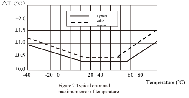
Accuracy error 1 | typical |
| ±0.3 |
| ℃ |
maximum | See figure 3. |
| ℃ |
repeatability |
|
| ±0.1 |
| ℃ |
sluggish |
|
| ±0.1 |
| ℃ |
Response time 6 | t 63% | five |
| 30 | s |
working range | extended 3 | -40 |
| eighty-five | ℃ |
Long time drift |
|
| <0.04 |
| ℃/yr |
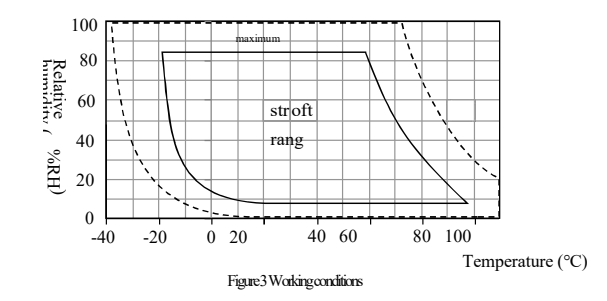
Suggested working environment
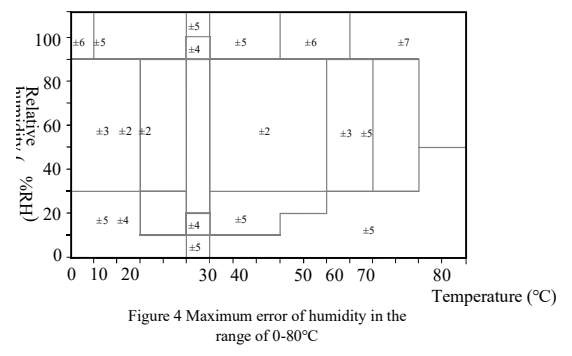
The recommended temperature and humidity range of the sensor is 5~60℃ and 20~80% RH, as shown in Figure 3.
Long-term exposure to the non-recommended range, such as high humidity, may cause temporary signal drift (e.g. > 80%RH, drift +3% RH after 60 hours). After returning to the recommended range environment, the sensor will gradually return to the calibration state. Long-term exposure to non-recommended range may accelerate the aging of products.
Accuracy of RH at different temperatures
electrical specification
Table 3 Electrical characteristics
parameter | condition | smallest | typical | maximum | unit |
supply voltage | typical | 2.0 | 3.3 | 5.5 | V |
Current supply, IDD5 | be in dormancy | - |
| 240 | nA |
measure |
| 340 |
| µA |
5 power consumption | be in dormancy | - |
| 0.8 | µW |
measure |
| 0.07 |
| mW |
average | - | 3.3 | - | µW |
correspondence | Two-wire digital interface, standard I2 C protocol
|
The power consumption given in Table 3 is related to temperature and supply voltage VDD. See Figures 5 and 6 for the estimation of power consumption. Please note that the curves in Figures 5 and 6 are typical natural characteristics, and there may be deviations.
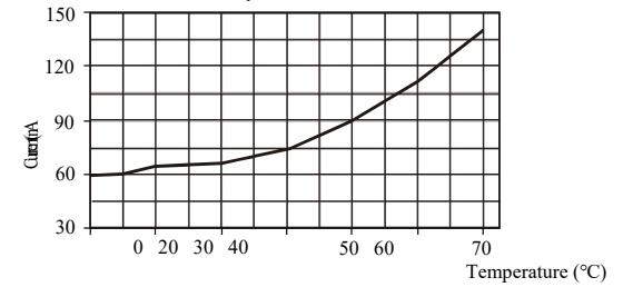
Figure 5 Typical supply current vs. temperature curve when VDD = 3.3V (sleep mode). These data deviate from the displayed values by about 25%.
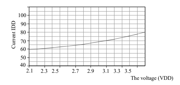
Fig. 6 Typical relationship curve between supply current and supply voltage at 25℃ (sleep mode).
Note: The deviation of these data from the displayed value may reach 50% of the displayed value. At 60℃, the coefficient is about 15 (compared with Table 3).
Packaging information
Sensor model | package | quantity |
XRTH22 | Tape packaging | 500 PCs/roll (MAX) |
Note:
1. This accuracy is the test accuracy of the sensor at 25°C and the power supply voltage is 3.3.V during the factory inspection.
2. The time required to reach 63% of the first-order response at 25°C and 1m/s airflow.
3. Normal working range: 0-80%RH, beyond this range, the sensor reading will deviate (after 200 hours under 90%RH humidity, drift <3%RH). The working range is limited to -40–80°C. 4. If there are volatile solvents, irritating odor tapes, adhesives and packaging materials around the sensor, the readings may be high.
5. The minimum and maximum values of supply current and power dissipation are based on the conditions of VDD = 3.3 V and T < 60°C.
6. The response time depends on the thermal conductivity of the sensor substrate
1 Application information
1.1 Storage environment
The temperature and humidity sensor should not contact with volatile chemicals, such as organic solvents or other inorganic compounds, otherwise it will lead to irreversible drift of humidity output reading. Therefore, it is suggested that the storage conditions of sensors sealed in ESD pockets should be: the temperature range is 10-50℃ (0-85℃ in a limited time); Humidity is 20-60% RH (sensor without ESD package). Sensors that have been taken out of the original packaging are recommended to be stored in antistatic bags made of PET/AL/CPE containing metal.
1.2 recovery processing
If the sensor drifts due to exposure to extreme working conditions. In order to restore it to the calibration state, the following processing can be performed. (1) drying: keeping at 80-85℃ and humidity < 5% RH for 10 hours; (2) Rehydration: keep it at 20-30℃ and humidity > 75% RH for 24 hours.
1.3 Temperature influence
Temperature will affect the relative humidity of the environment. Therefore, in the process of measuring the same humidity, all the sensors should be at the same temperature. Secondly, during testing, the temperature of the tested sensor should be the same as that of the reference sensor.
On the same printed circuit board, in order to minimize the influence of heat transfer, the sensor should be isolated from the electronic components that are prone to heat as much as possible.
Too high measurement frequency will also affect the measurement accuracy, because the temperature of the sensor itself will rise with the increase of measurement frequency. If its own temperature rise is lower than 0.1℃, the activation time of XRTH22 should not exceed 10% of the measurement time. It is recommended to measure the data every 2 seconds.
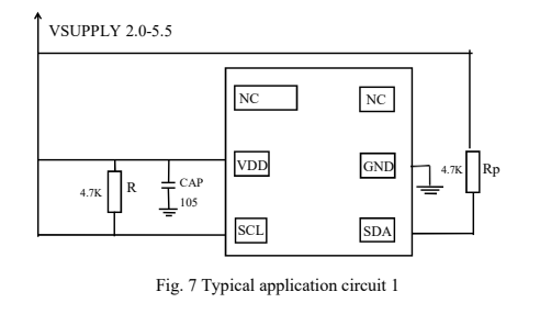
1.4 Typical application circuit
In order to improve the stability of the system, the following power supply controllable scheme is provided:
1.5 And the choice of sealing materials.
In order to avoid the response time increase and hysteresis of the sensor caused by moisture absorption by surrounding materials, the following materials are recommended: metal materials, LCP, POM (Delrin), PEEK, PVDF, PTFE (Teflon), PP, Pb, PPS, PSU, PE, PVF.
When packaging electronic components, the method of filling epoxy resin or silicone resin can be used. However, the gas released by the packaging material may cause the WHT20 to be polluted. Therefore, the sensor should be finally assembled in a well-ventilated place, or the polluted gas can be released before packaging.
1.6 wiring
To avoid signal crosstalk and communication failure caused by wiring, do not parallel or close the SCL and SDA signal lines to each other. You can place VDD and/or GND between the SCL and SDA signal lines or use shielded cables.
Signal integrity
Reducing SCL frequency can improve the integrity of signal transmission. Add a 100 nF between the power supply pins (VDD, GND)
The decoupling capacitor is used for filtering.
1.7 Equipment function mode
XRTH22 has two operating modes: sleep mode and measurement mode. After power-on, XRTH22 enters the sleep mode, in which XRTH22 waits for I2C input to configure the conversion time, reads the battery status, triggers the measurement, and reads the measured value. After the measurement, XRTH22 returns to the sleep mode.
1.8 Welding instructions
I/O pads of SMD are made of copper lead frame planar substrate, except that these pads are exposed to the outside for mechanical and circuit connection. When using, I/O pads and bare pads need to be soldered on PCB. To prevent oxidation and optimize welding, the solder joints at the bottom of the sensor are plated with Ni/Au.
On PCB, the length of I/O contact surface should be 0.2~0.3 mm larger than the I/O package pad of XRTH22, and the width should be 0.1~0.2 mm larger than the package pad. The inner part should match the shape of I/O pad, and the ratio of pin width to SMD package pad width is 1:1, as shown in Figure 8.
For the design of screen plate and solder mask, it is recommended to use copper foil definition pad (SMD) with solder mask opening larger than metal pad. For SMD pads, if the gap between copper foil pad and solder mask is 60m-75m, the opening size of solder mask should be larger than the pad size of 120m-150m. The square part of the package pad should match the corresponding square solder mask opening to ensure that there is enough solder mask area (especially at the corner) to prevent solder from intersecting. Each pad must have its own solder mask opening, which is adjacent to
A solder mask network is formed around the bonding pad.
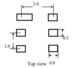
Fig. 8 recommended design size of XRTH22 20 PCB (unit: mm), and the peripheral dotted line is the external size of SMD package.
For solder printing, it is recommended to use laser-cut stainless steel mesh with electronically polished trapezoidal wall, and the recommended thickness of steel mesh is 0.125mm. The size of the steel mesh for the pad part must be 0.1 mm longer than the PCB pad and placed 0.1 mm away from the package center. The steel mesh of the bare pad should cover 70 %-90% of the pad area—that is, 1.4 mm×2.3 mm in the center of the heat dissipation area.
Due to the low mounting height of SMD, it is recommended to use no-clean type 3 solder 9, and purify it with nitrogen during reflow.
Please use a standard reflow oven to weld XRTH22. The sensor conforms to IPC/JEDEC J-STD-020D welding standard. The best reflow temperature is below 200℃, and the ultimate welding temperature that can be borne is 260℃. It should be noted that the contact time should be less than 30 seconds at the highest temperature of 260℃ (see Figure 9). It is recommended to use low temperature of 180℃ in reflow soldering.
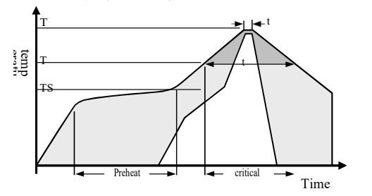
Fig. 9 JEDEC standard welding process diagram, Tp<=260 ℃, tp<30 sec, lead-free welding. TL<220 ℃, tl<150 sec, the speed of temperature rise and fall during welding should be <5 ℃/sec。
Note: After reflow soldering, the sensor should be stored in the environment of > 75% RH for at least 24 hours to ensure the rehydration of the polymer. Otherwise, the sensor reading will drift. You can also rehydrate the sensor by placing it in the natural environment (> 40% RH) for more than 5 days. Low temperature reflow soldering (such as 180℃) can reduce hydration time.
It is not allowed to flush the circuit board after welding. Therefore, customers are advised to use "no-wash" solder paste. If the sensor is used in corrosive gas or condensed water is produced (such as high humidity environment), both the pin pad and PCB need to be sealed (such as using conformal coating) to avoid poor contact or short circuit.
2 interface definition
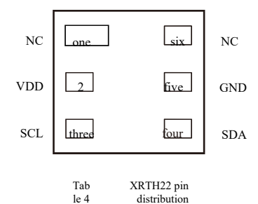
name | pin | paraphrase |
NC | one | Stay suspended |
VDD | 2 | Power supply, the power supply range is 2.0-5.5 V, and the recommended voltage is 3.3 V. |
SCL | three | I2C serial clock, bidirectional, used for communication synchronization between microprocessor and WHT20. |
SDA | four | I2C serial data, bidirectional, used for input and output of sensor data. |
GND | five | Ground power supply |
NC | six | Stay suspended |
Note: 1. In order to prevent the current from leaking into the signal line (SCL/SDA) and causing the chip to be in a non-working state after being powered on, VDD should be powered on before SDA and SCL or synchronously.
2. To ensure communication security, the effective time of SDA should be extended to TSUand THD before and after the rising edge of SCL (refer to Figure 10).
3electrical specification
3.1 Absolute maximum rating
The absolute maximum rating of XRTH22 is shown in Table 5. In addition, Table 5 also provides information such as pin input current. If the test condition exceeds the nominal limit, the sensor needs to be equipped with additional protection circuit.
Table 5 Absolute maximum electrical rating
parameter | smallest | maximum | unit |
VDD to GND | -0.3 | 5.5 | V |
Digital I/O pin (SDA,SCL) to GND | -0.3 | VDD+0.3 | V |
Input current of each pin | -10 | 10 | mA |
Note: Long-term exposure to the absolute maximum rating may affect the reliability of the sensor.
3.2 I2C interface voltage
Electrical characteristics, such as power consumption, high and low voltage of input and output, depend on the power supply voltage.
Table 6 DC characteristics of digital input and output pads. Unless otherwise stated,
VDD=2.0 V to 5.5 V, T =-40 ℃ to 85 ℃
parameter | condition | smallest | typical | maximum | unit |
Output low voltage | VOL | VDD = 3.3 V Reverse current 3mA | 0 | - | 0.4 | V |
Output high voltage | VOH |
| 0.7VDD | - | VDD
| V |
Output sink current | IOL |
| - | - | -4 | mA |
Input low voltage | VIL |
| 0 | -
| 0.3VDD | V |
Input high voltage | VIH |
| 0.7VDD | - | VDD | V |
incoming current |
| VDD = 5.5 V,VIN = 0 V to 5.5 V | - | - | ±1 | uA |
3.2 I2C interface timing
Table 7 Timing Characteristics of I2C Fast Mode Digital Input/Output
parameter | I2C typical mode | I2C high speed mode | unit |
MIN | MAX | MIN | MAX |
I2C clock frequency | fSCL | 0
| 100 | 0 | four hundred | KHz |
Start signal time | tHDSTA | 0.1 |
|
|
| μs |
SCL clock high level (width) | tHIGH | 4.7 |
| 1.3 |
| μs |
SCL clock low level (width) | tLOW | 4.0 |
| 0.6 |
| μs |
Saving time of data (relative to SCL, SDA edge) | tHDDAT | 0.09 | 3.45
| 0.02
| 0.9
| μs |
Setting time of data (relative to SCL, SDA edge) | tSUDAT | 250 |
| 100
|
| μs |
BUS idle time before stopping and starting | tBUS |
|
| one |
| μs |
Note: (1) Both pins are measured from 0.2 VDD and 0.8 VDD. (2) The above I2C timings are determined with the following internal delays: the internal SDI input pin is delayed with respect to the SCK pin, typical The value is 100 ns; the internal SDI output pin is delayed relative to the falling edge of SCK, typically 200 ns.
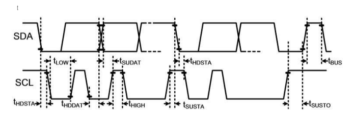
Fig. 10 The timing diagram and abbreviations of digital input/output terminals are explained in Table 7.
The thicker SDA line is controlled by the sensor, and the ordinary SDA line is controlled by the single chip microcomputer.
Please note that the SDA effective read time is triggered by the falling edge of the previous conversion.
4 Communication of sensors
XRTH22 communicates as a slave of I2C bus interface. After power-on, the sensor needs at most 20 ms (at this time, SCL is at high level) to reach the sleep mode, and when the host sends a command, the temperature and humidity measurement can be started.
4.1 Start/stop timing
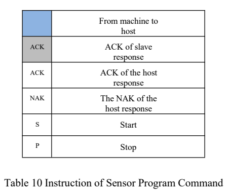
Each transmission sequence Starts with a start state and ends with a Stop state, as shown in (1) and (2) in Figure 11.
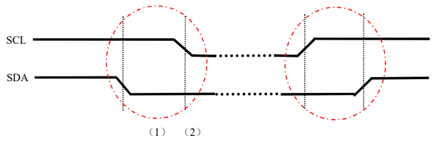
Fig. 11 start transmission (s) and stop state (p)
Note:
(1) When SCL is at a high level, SDA is converted from a high level to a low level. Start state is a special BUS state controlled by the master, which indicates the start of slave transmission (after start, the bus is generally considered to be busy).
(2) When SCL is high, the SDA line changes from low level to high level. Stop state is a special BUS state controlled by the master, indicating the end of slave transmission (after stop, the bus is generally considered to be idle).
4.2 Transmission of commands
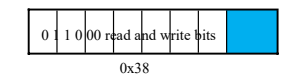
The transmitted I2C first byte includes 7 bits of I2C device address 0x38 and an SDA direction bit X (read R:' 1' and write W:' 0'). After the falling edge of the 8th SCL clock, the SDA pin (ACK bit) is pulled low to indicate that the sensor data is received normally.
As shown in the basic commands in Table 8, after issuing the' 1011' 1110' command, the representative will be initialized, while after issuing the' 1010' 1100' command, the representative will measure the temperature and humidity, and the MCU must wait until the measurement is completed.
Table 8 Basic commands
code | order | meaning |
1011’1110 (0xBE) | Initialization command | Keep the host |
1010’1100 (0xAC) | Trigger measurement | Keep the host |
Table 9 shows the status bits returned by the slave. Different bits represent different meanings, and their meanings are not the same.
Table 9 Description of status bits
Bit | meaning | describe |
Bit[7] | Busy indication (busy indication) | 1-the equipment is busy and in the measuring state. 0-The equipment is idle and in a dormant state. |
Bit[6:5] | Current working mode | 00 is currently in NOR mode 01 is currently in CYC mode. 1x is currently in CMD mode. |
Bit[4] | Memory data integrity indication | 1-indicates that the integrity test failed. 0-indicates that the memory data integrity test has passed. |
Bit[3] | Calibration enable bit CAL Enable | 1-the calibration calculation function is enabled, and the output data is the calibrated data. 0-The calibration calculation function is disabled, and the output data is the original data output by ADC. |
Bit[2:0] | reserve | reserve |
4.3 Sensor reading process
1. Wait 40 ms after power-on. Before reading the temperature and humidity value, you should first see whether the calibration enable Bit[3] of the status word is.
1 (a one-byte status word can be obtained by sending 0x71). If it is not 1, a 0xBE command (initialization) will be sent. This command parameter has two bytes, the first byte is 0x08 and the second byte is 0x00.
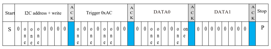
2. Send the 0xAC command (trigger measurement) directly. This command parameter has two bytes, the first byte is 0x33, and the second byte is 0x00.
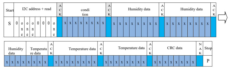
3. Wait 75 ms for the measurement to be completed. The busy status Bit[7] is 0, and then you can read six bytes (you can read it by sending 0X71).
4. Calculate the temperature and humidity value.
Note: In the first step, the calibration status check only needs to be done at power-on, and no operation is needed in the normal acquisition process.
Trigger measurement data
Read temperature and humidity data
5 Signal conversion
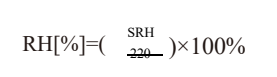
5.1 Relative humidity conversion
The relative humidity RH can be calculated by the following formula according to the relative humidity signal SRH output by SDA (the result is expressed as% RH).
5.2 Temperature conversion
T can be calculated by substituting the temperature output signal ST into the following formula (the result is expressed as temperature℃).
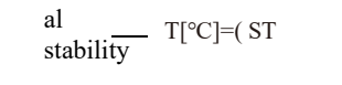
6 environmental stability
When the sensor is used in equipment or machinery, it is necessary to place the sensor at the same temperature and humidity as the sensor for reference. In order to prevent the error caused by insufficient test time, when the sensor is placed in equipment or machinery, it is necessary to ensure sufficient measurement time through program design.
7 package
XRTH22 is packaged in a double-sided leadless flat package. The sensor chip is made of copper lead frame plated with Ni/Au. The weight of the sensor is about 19 mg, and the specific size of the sensor is shown in Figure 12.
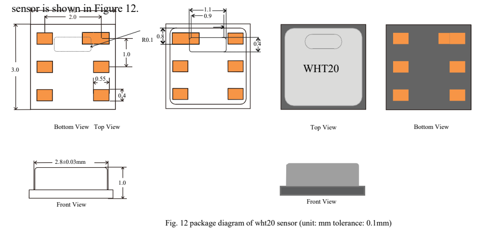
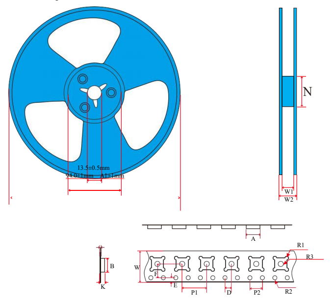
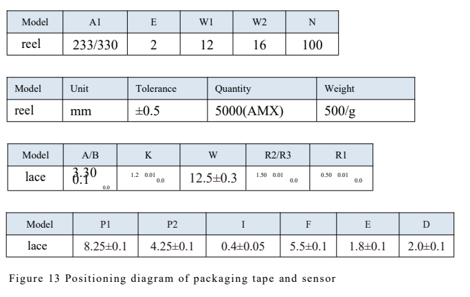
XRTH22 is wrapped in tape and sealed in an antistatic ESD bag. The standard package size is 5000 pieces per roll. For WHT20 package, the rear 440 mm(55 sensor capacity) and the front 200 mm(30 sensor capacity) of each reel are empty packages.
The package diagram with sensor positioning is shown in Figure 13. The reel is placed in an anti-static pocket.
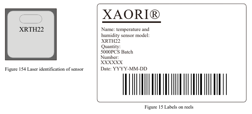
8 Tracking information
All XRTH22 sensor surfaces are marked with laser. See figure 14. There is a label attached to the reel, as shown in Figure 15, and other tracking information is provided.
matters need attention
Warning, personal injury
Do not apply this product to safety protection devices or emergency stop equipment, or any other application where personal injury may occur due to the failure of this product. Do not use this product unless there is a special purpose or authorization to use it. Please refer to the product data sheet and application guide before installing, handling, using or maintaining the product. Failure to follow this advice may result in death and serious personal injury.
If the buyer is going to buy or use the products of Weisheng without any application license and authorization, the buyer will bear all the compensation for personal injury and death caused thereby, and exempt any claims that may arise from the managers and employees of Weisheng Company, its affiliated subsidiaries, agents, distributors, etc., including various costs, compensation fees, lawyers' fees, etc.
ESD protection
Due to the inherent design of components, it is sensitive to static electricity. To prevent the injury caused by static electricity or reduce the product performance, please take necessary anti-static measures when applying this product.
quality assurance
Our company provides a 12-month (1-year) quality guarantee to the direct buyers of its products (calculated from the date of delivery), which is based on the technical specifications in the data sheet of this product published by Weisheng. If the product is proved to be defective within the warranty period, our company will provide free repair or replacement. Users need to meet the following conditions:
1. The product shall be notified to the Company in writing within 14 days after the defect is found;
2. The defects of this product will help to find the deficiencies in the design, materials and technology of our company;
3. The product should be sent back to our company at the buyer's expense;
4. The product should be within the warranty period.
Our company is only responsible for the products that are defective when they are used in situations that meet the technical conditions of the products. The company does not make any guarantee, guarantee or written statement about the application of its products in those special application occasions. At the same time, our company makes no commitment to the reliability of its products applied to products or circuits.
 +86-0755-29898410 +86-0755-29898460
  ron@xaori.net