Product Detail
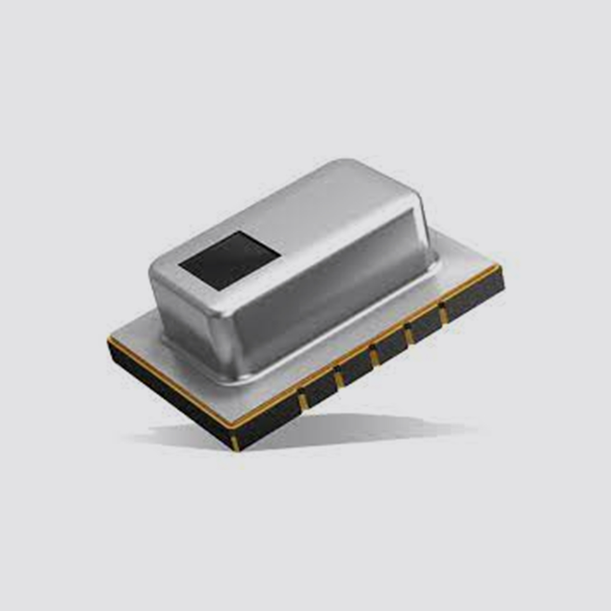
Surface Mount Type
AMG88xx(High performance type)
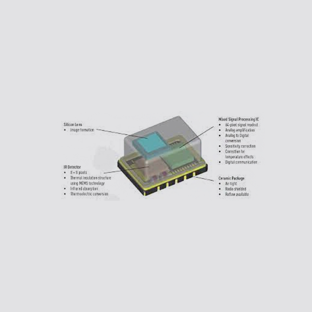
High Precision Infrared Array Sensor based on Advanced
MEMS Technology
Feature
● Temperature detection of two-dimensional area: 8 × 8 (64 pixels)
● Digital output (capability of temperature value output)
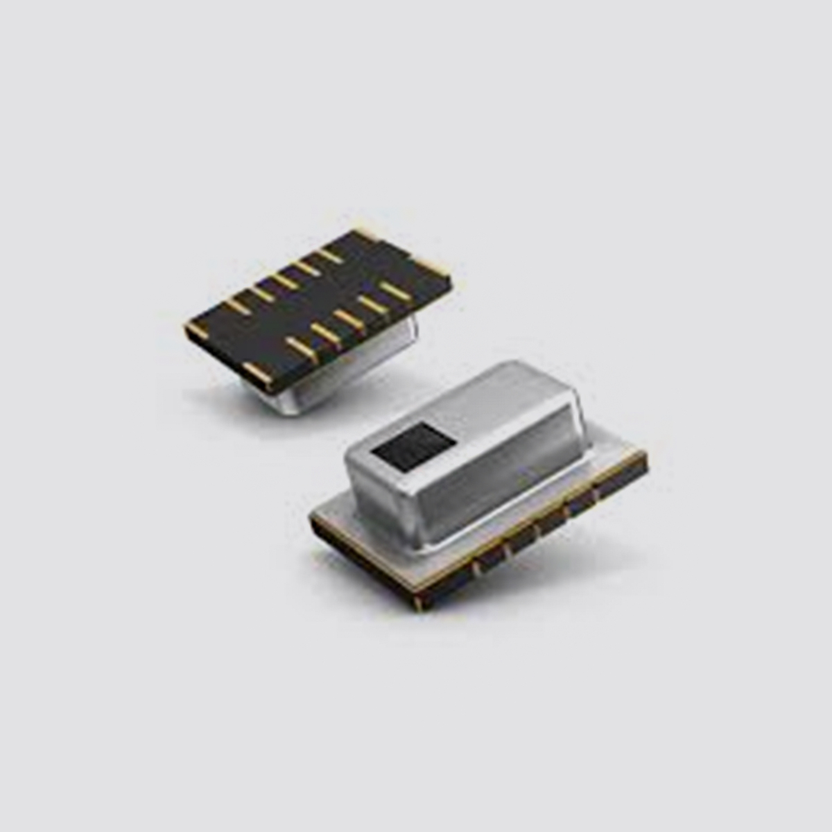
● Compact SMD package (adaptively to reflow mounting)
● RoHS compliant
Typical applications
● Home appliances (Microwaves and air-conditioners)
● Building automation (People counting, Air conditioning control)
● Home automation (People detection)
● Factory automation (Fault prevention)
Ordering information
Types
Tape and reel package : 1,000 pcs.
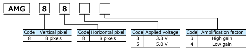
Product name | Number of pixel | Operating voltage | Amplification factor | Part number |
Infrared array sensor Grid-EYE | 64 (Vertical 8 × Horizontal 8 Matrix) | 3.3 V | High gain | AMG8833 |
Low gain | AMG8834 |
5.0 V | High gain | AMG8853 |
Low gain | AMG8854 |
Rating
Item | Performance |
High gain | Low gain |
Applied voltage | 3.3 V ± 0.3 V or 5.0 V ± 0.5 V |
Temperature range of measuring object | 0 ℃ to 80 ℃ +32 ℉ to +176 ℉ | −20 ℃ ~ 100 ℃ –4 ℉ to +212 ℉ |
Operating temperature range | 0 ℃ to 80 ℃ +32 ℉ to +176 ℉ | −20 ℃ ~ 80 ℃ –4 ℉ to +176 ℉ |
Storage temperature range | −20 ℃ to 80 ℃ –4 ℉ to +176 ℉ | −20 ℃ ~ 80 ℃ –4 ℉ to +176 ℉ |
Absolute maximum ratings
Item | Absolute maximum ratings | Terminal |
Applied voltage | −0.3 V to 6.5 V | VDD |
Input voltage | −0.3 V to VDD +0.3 V
| SCL, SDA, AD_SELECT |
Output sink current | −10 mA to 10 mA | INT, SDA |
Static electricity (Human Body Model) | 1 kV | All terminals |
Static electricity (Machine Model) | 200 V | All terminals |
Characteristics
Item | Performance |
High gain | Low gain |
Temperature accuracy | Typical ± 2.5 ℃ ±4.5 ℉ | Typical ± 3.0 ℃ ±5.4 ℉ |
NETD *1 | Typical 0.05 K (in 1 fps setting*2) Typical 0.16 K (in 10 fps setting) |
Viewing angle | Typical 60 ° |
Current consumption | Typical 4.5 mA(normal mode) Typical 0.2 mA(sleep mode) |
Setup time | Typical 50 ms(Time to enable communication after setup) Typical 15 s(Time to stabilize output after setup) |
*1: It is calculated from 4 pixels of centers.
*2: fps: frame per second
Performance
Item | Performance |
Number of pixel | 64 (Vertical 8 × Horizontal 8 Matrix) |
External interface | I2C |
Frame rate | Typical 1 fps or 10 fps |
Operating mode*3 | Normal Sleep |
Output mode | Temperature output |
Calculate mode | No moving average or Twice moving average |
Temperature output resolution | 0.25 ℃ 0.45 ℉ |
Number of sensor address | 2(I2C slave address) |
Thermistor output temperature range | −20 ℃ to 80 ℃ –4 ℉ to +176 ℉ |
Thermistor output resolution | 0.0625 ℃ 0.1125 ℉ |
*3: Normal Mode : normal operation mode; Sleep Mode: detection is off (output and data reading not possible)
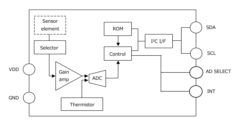
Internal circuit
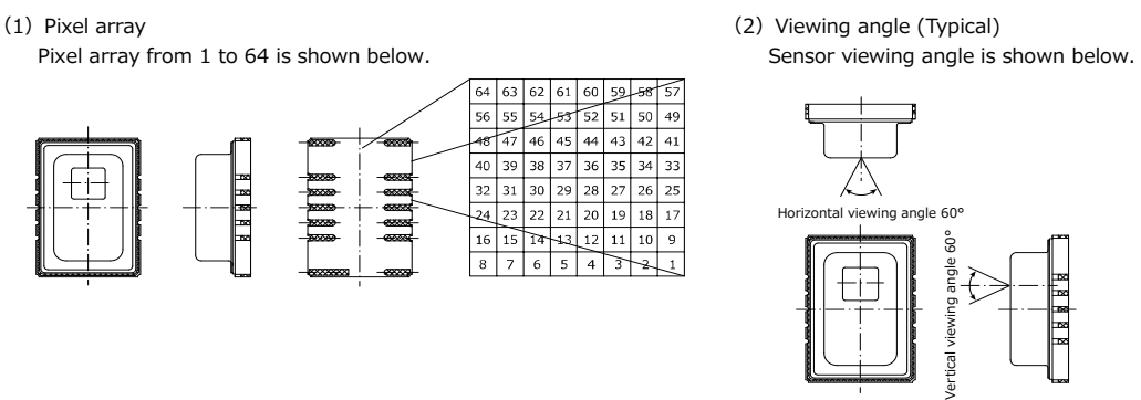
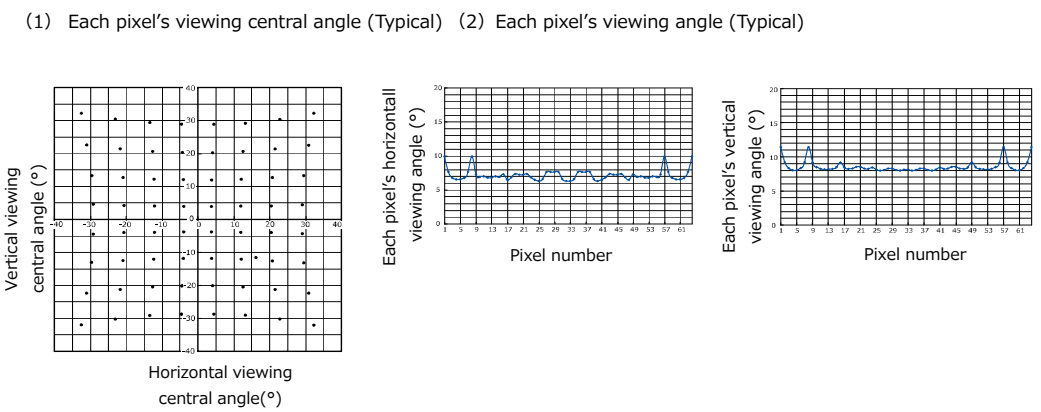
Pixel array and viewing angle
Optical properties
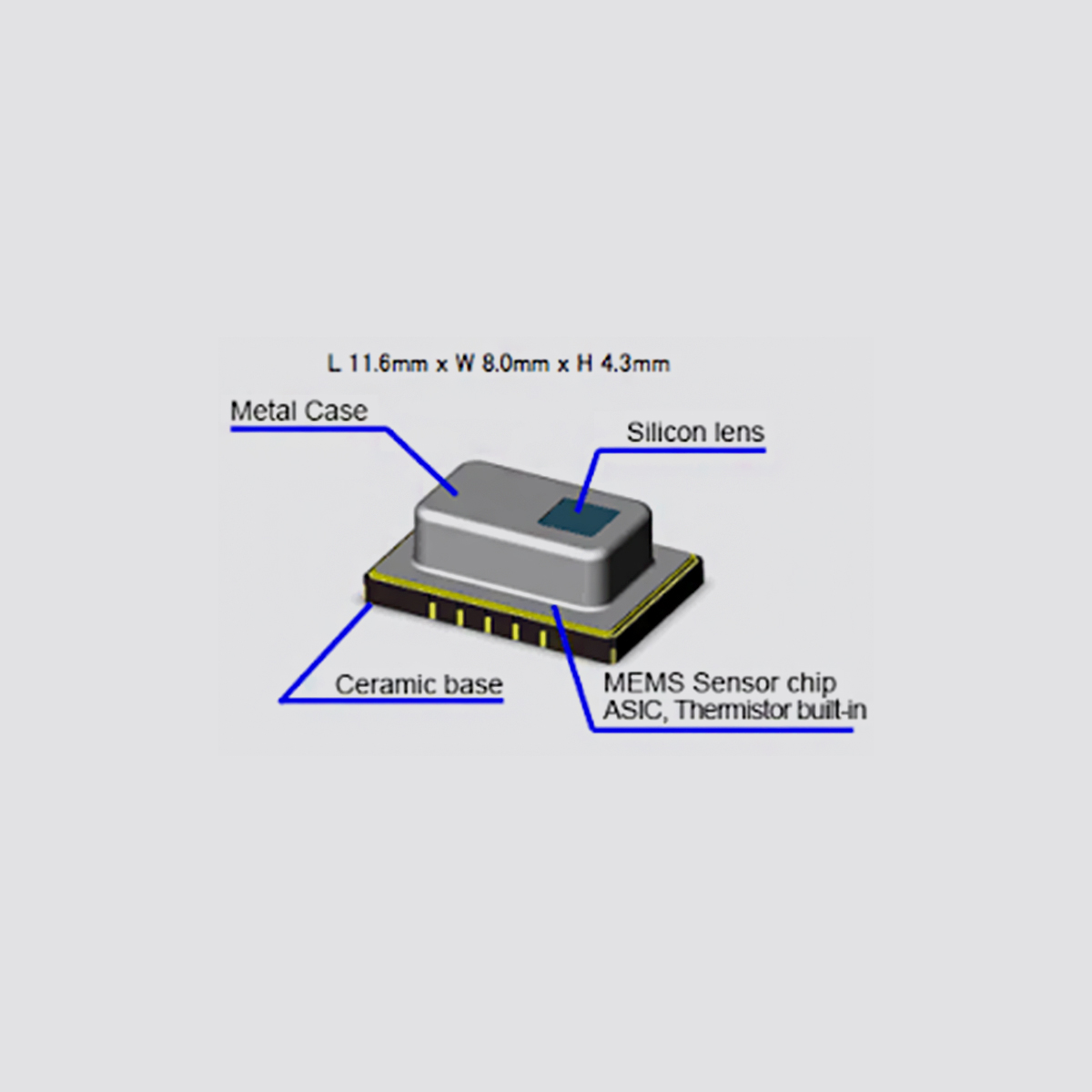
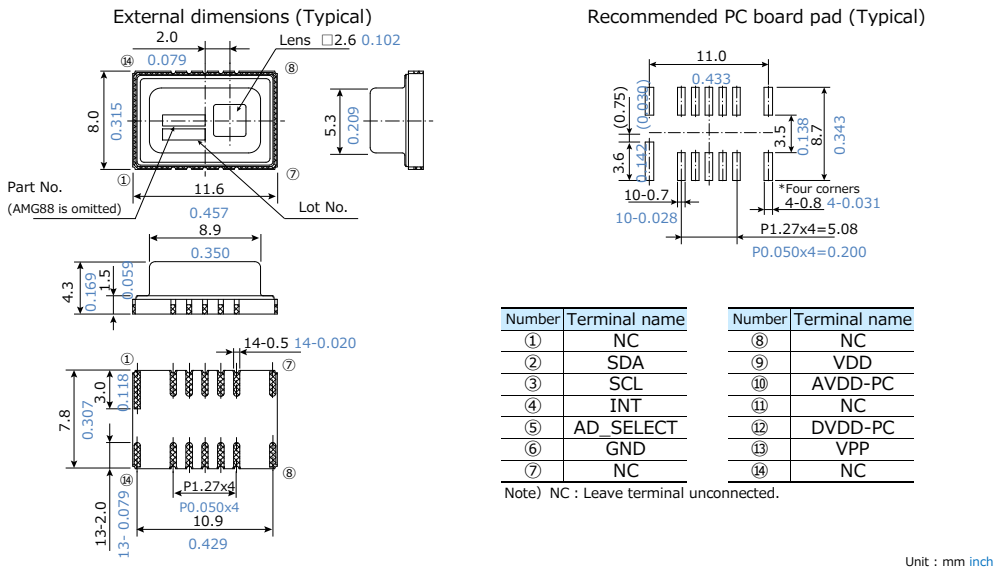
Dimensions
External circuit
(1)In case of setting I2C slave address of the sensor 1101000
※ Connect terminal 5 (AD_SELECT) to GND.
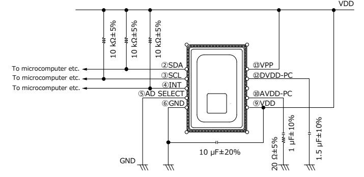
(2)In case of setting I2C slave address of the sensor 1101001
※ Connect terminal 5 (AD_SELECT) to VDD.
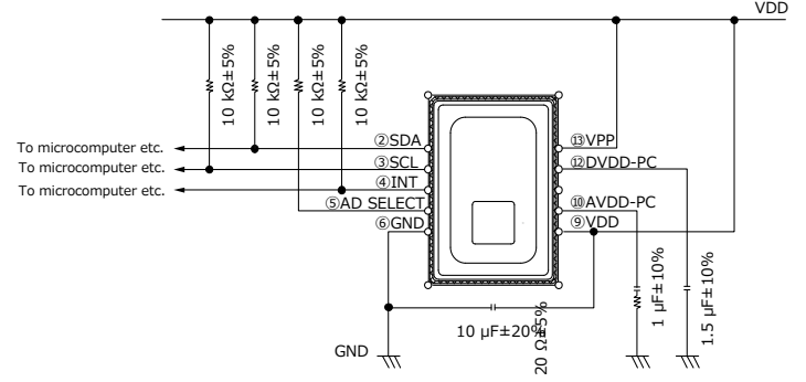
・ This circuit is an example to drive Infrared Array Sensor “Grid-EYE”, so that our company will not take any responsibility of loss which is due to this circuit.
・ The wiring connected to VDD are same electrical potential (same supply voltage).
・ If there is a difference of electric potential between the terminals, it can be cause of breakdown.
・ Connect wiring to solid GND with wide and short pattern on PCB.
・ If wiring pattern is designed thin and long, temperature accuracy will be degraded.
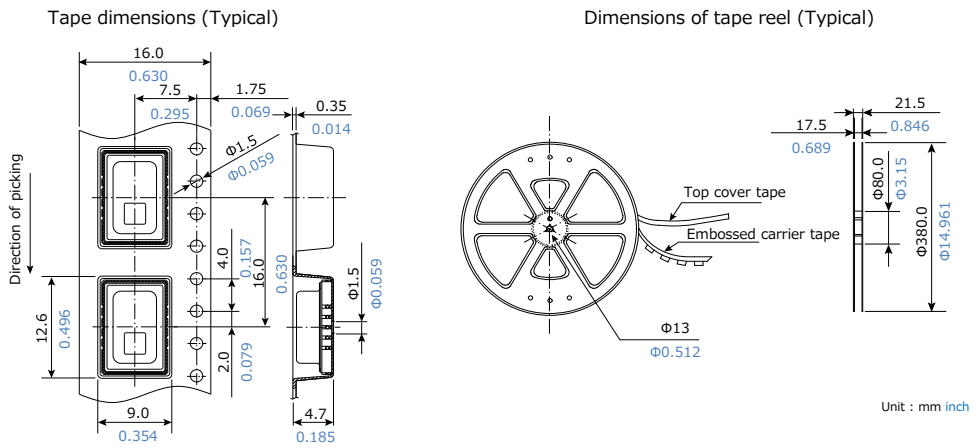
Packing format (Tape and reel)
Safety Precautions
■ Head the following precautions to prevent injury or accidents.
(1) We take no responsibility for troubles caused by the product usage that is not specified in this specification.
Using the sensors in any way which causes their specifications to be exceeded may generate abnormally high levels of heat, emit smoke, etc., resulting in damage to the circuitry and possibly causing an accident.
(2) Before connecting a connector, check the pin layout by referring to the connector wiring diagram, specifications diagram, etc., and make sure that the connector is connected properly. Take note that mistakes made in connection may cause unforeseen problems in operation, generate abnormally high levels of heat, emit smoke, etc., resulting in damage to the circuitry.
(3) If the module heats up abnormally or smells abnormal, stop using it immediately by turning off the main power supply of the device etc.
(4) The fact remains that electrical components and devices generally cause failures at probability. Furthermore, their durability varies with use environments or use conditions. In this respect, we ask you to check for actual electrical components and devices under actual conditions before use without fail.
(5) Failure modes of sensors include short-circuiting, open-circuiting and temperature rises. If the failure of the product is considered to cause a personal injury or death or property damage, the safety rate should be added to the specified values shown in this specifications and please consider the fail-safe design in the following considerations and ensure safety.
・ Provide protection circuits and protection devices to ensure system safety.
・ Provide of a redundant circuit so that a malfunction does not make the system unsafety.
(6) When a dogma shall be occurred about safety for this product, be sure to inform us rapidly, operate your technical examination.
Notes
■ Precaution for fundamental structure of sensor
Infrared Array Sensor is a thermopile type infrared sensor which detects the amount of infrared rays. Below conditions generally degrade the temperature accuracy.
Carefully check the performance and stability under actual use conditions, and perform temperature corrections when necessary.
(1) When heating elements exist near the mounting position of the sensor.
(2) When the sensor is exposed to cold or hot air.
(3) When the temperature of the sensor body rapidly changes.
(4) When substances (e.g., glasses, acrylics or steams), which hardly transmit a far infrared ray, exist between the sensor and the detected object.
(5) When substances (e.g., foreign substances or water), which hardly transmit a far infrared ray, adhere to the lense of the sensor.
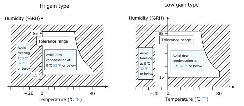
■ Use environment
(1) Temperature: See the specifications
(2) Humidity: 15 % to 85 % R.H. (Avoid freezing and dew condensation)
(3) Atmospheric pressure: 86 to 106 kPa
(4) Vibrations and shocks may damage the sensor, and cause malfunction and performance deterioration. If loads and shocks are applied on the lense, the damaged sensor may cause malfunction and performance deterioration.
(5) The product is not water/splash-proof. Perform water/dust-proofing and dew condensation / freezing countermeasures in accordance with use environment. When dew condensation occurs, responsiveness of heat source detection may delay for several seconds. Be careful to solder migration caused by adhesion of water droplets on solder parts.
(6) Avoid use and storage in the corrosive gas (organic solvent, sulfurous acid and hydrogen sulfide gases) to avoid malfunction and performance deterioration.
(7) Use surge absorbers as applying the external surge voltage may damage the internal circuit.
(8) Malfunction may occur near electric noises from static electricity, lightning, broadcast or amateur radio stations and mobile phones.
(9) The sensor can continuously operate within the range of using ambient temperature (using ambient humidity). However, ensure that humidity is within the range described in the following page as humidity varies according to temperature.
Avoid the continuous operation near the operational limit. The temperature range does not guarantee the durability.
Notes
■ Mounting
Use the land of the printed-circuit board on which the sensor is securely fixed. The recommended printed-circuit board is FR4 (thickness 1.6 mm 0.063 inch). When mounting on the deprecated circuit board, carefully check the performance and quality under actual use conditions before use.
(1) A large noise on the power supply may cause malfunction. Place the recommended capacitor near the sensor (within 20 mm 0.787 inch of the wiring pattern length) between sensor input terminals (VDD-GND) to secure power superimposed noise resistance. Test with the actual machine and reselect the capacitor with optimal capacitance.
(2) Prevent the metal part of other electronic components from contacting with the sensor body as the upper face (where part numbers are imprinted) of the sensor is GND.
■ Soldering
Due to the thermal capacity of the infrared array sensor is low, therefore, take steps to minimize the effects of external heat.
Damage and changes to characteristics may occur due to heat deformation.
(1) Manual soldering
Set the soldering tip from 350 to 400 ℃ (30 - 60 W), and solder within 3 seconds or less. Note that output may be changed
if the load is applied to the terminals when the soldering carefully clean the tip of soldering iron.
(2) Reflow soldering
・ Solder coating
We recommend the screen solder printing method as the method of cream. Halogen type (Chlorine type, Bromine type , etc.) or other high-activity flux is not recommended as the residue may affect performance or reliability of resistors.
・ Mounting of sensor
Self alignment may not always work as expected, therefore, be carefully the position of the terminals and pattern.
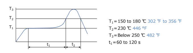
・ The recommended reflow temperature profile
The recommended reflow temperature profile conditions are given below. The temperature of the profile is assumed to be a value measured with the printed wiring board of the product terminal neighborhood. The temperature of PCB near this product terminal at the time of mounting changes depending on PCB design. Therefore, please confirm the temperature of PCB near this product terminal to become the specified temperature profile when this product be mounted on the PCB.
(3) Solder reworking
Finish reworking in one operation for reworking of the solder bridge, use a soldering iron with a flat tip do not add more flux when reworking Refer the conditions of manual soldering to rework.
(4) Coating of PCB
To prevent the insulation of the PC board after soldering, not to place the chemicals on lens of the sensor when coating.
(5) Dividing of PCB
When you cut, fold, or fix with screw the PCB after mounting the sensor, not to stress to the sensor and the soldered parts.
(6) Structure of sensor terminals
The sensor terminals are designed to be exposed, so contact of the terminals with metal shards and the like will cause output errors. Therefore, be careful not to touch the terminals with the metal piece or the hand.
(7) Both-side soldering
When you do the reflow solder to the back of the PC board after the reflow of the sensor, execute fixed processing, or instance, with the adhesive etc.
(8) When handling this product, do not touch it with bare hands. Please wear gloves.
■ Wire connection
Correctly wire as in the connection diagram. Reverse connection may damage the product and degrade the performance.
Do not use empty terminals. Such use may damage the sensor. For cable wiring, use shield wires with possibly short wiring lengths to prevent the influence of the noise.
■ Cleaning
If the dirt or water droplets is attached to the lens, wipe it with soft cloth. The lens is damaged when strongly rubbed, and causes the characteristic deterioration. Avoid ultrasonic cleaning since this may cause breaks or disconnections in the wiring.
■ Transportation and storage
(1) Extreme vibration and shock during transport will damage the sensor. Handle the outer box and reel with care.
(2) Storage under extreme conditions will cause soldering degradation, external appearance defects, and characteristic deterioration.
The following storage conditions are recommended.
Temperature:0 ℃ to 45 ℃ 32 ℉ to 113 ℉
Humidity:70 %RH
Others:Not storage in places full of corrosive gases such as sea breeze, Cl2, H2S, NH3, SO2, and NOx, minimal dust.
Not storage in places exposed to direct sunlight.
(3) The sensors are sensitive to moisture and come in moisture-proof packages.
Observe the following cautions when storing.
・ After the moisture-proof package is unsealed, take the sensors out of storage as soon as possible
(within 1 week, less than 30 ℃, less than 60 %R.H.,)
・ If the sensors are to be left in storage for a considerable period after the moisture-proof package has been unsealed, keep them in another moisture-proof bag containing silica gel (within 3 months at the most).
(4) When using the product stored for a long time, dry the package before reflow work.
・ When mounting with solder, if thermal stress is applied to sensors that have absorbed moisture, the moisture will vaporize, swelling will occur, and the inside of the package will become stressed. This may cause the package surface to blister or crack. Therefore, take caution and observe the soldering conditions.
■ Other handling cautions
(1) To assure reliability, check the sensor under actual loading conditions. Avoid any situation that may adversely affect its performance.
(2) This product may malfunction if dropped on its own before it is installed. Do not use if this happens.
(3) If the sensor get high frequency vibration, it can be cause of breakdown. When the product get impulse like below, do not use it.
・ Touch to a object made of metal
・ Touch of mutual sensors
(4) Since static charge can damage the sensor, bear in mind the following handling precautions.
・ Plastic containers should not be used to store or transport the sensors since they readily become charged.
・ Store or transport the product in an environment that hinders the occurrence of static electricity (for example, places with 45 % to 60 % humidity) and protect the product using electrically conductive packaging.
・ Implement static electricity prevention measures once the product packaging has been opened.
(5) Do not use this product which has been disassembled or remodeled.
(6) Do not reuse this product after removal from the mounting board.
■ Special remarks
Although the best attention will be paid for the quality controls of the products, consider the followings contents.
(1) This product is designed to use in general applications at general electric equipment (Household electric appliances, AV products, office equipment, information and equipment, etc.). This product is not an important safety product.
This product is not equipped with fail proof/fault diagnosis functions. If there is possibilities to occur failure or malfunction of this product which may cause unsafe event such as (a)~(d) and damage to personnel’s life, body and property, we will be not responsible for any loss or damage caused by the use of products.
(a) Fire accident(Fire, smoke)
(b) Electrocution(Electric shock)
(c) Damages(Fall down/Explosion/Poisoning)
(d) Fire/electrocution/damages at life end
(2) This specification shows the quality and performance of a unit component. Before adoption, be sure to evaluate and verify the product mounting it in your product.
(3) Unless otherwise stipulated by both parties, the warranty period of our products is one year after their purchase by you or after their delivery to the location specified by you.
(4) In the event that we are found to blame for any failures or defects in our products during the warranty period, we will provide replacements or supply the necessary spare parts or replace and/or repair the defective sections free of charge and with all due speed at the location where the products concerned were purchased or delivered. However, the following failures and defects are not covered by the warranty:
・ When the failure or defect was caused by a specification, standard, handling method, etc. which was specified by you.
・ When the failure or defect was caused after purchase by you or delivery to your premises by an alteration in construction, performance, specification, etc. which did not involve us.
・ The case that the product condition changed by handling, storage and / or transportation after delivery.
・ When the failure or defect was caused by a phenomenon that could not be predicted by the technology that was being applied in practice either after purchase by you or at the time when the contract was signed.
・ When the use of our products deviated from the scope of the conditions and environment set forth in the specifications.
・ When, after our products were incorporated into your products or equipment for use, damage resulted which could have been avoided if your products or equipment had been equipped with the functions, construction, etc. the provision of which is accepted practice in the industry.
・When the failure or defect was caused by a natural disaster or other force majeure. The terms and conditions of the warranty here set forth apply solely to the warranty of the discrete products which were purchased by you or delivered to your premises, and they do not cover any damage induced by their failure or defects.
(5) The products and specifications described in this document are subject to change (including specification changes and production suspension) due to product improvements. When considering a using a new products, please contact our sales office to confirm that the information in this specifications is up-to-date.
(6) In connection with the products you have purchased from us or with the products delivered to your premises, we ask that you perform an acceptance inspection with all due speed and, in connection with the handling of our products both before and during the acceptance inspection, we ask that you give full consideration to the control and preservation of our products.
(7) As to the disposal of the product, check the method of disposal in each country or region where the product are incorporated in your products to be used.
(8) The technical information in this specification provides examples of our products' typical operations and application circuits. We do not guarantee the non-infringement of third party's intellectual property rights and we do not grant any license, right, or interest in our intellectual property.
 +86-0755-29898410 +86-0755-29898460
  ron@xaori.net