Product Detail
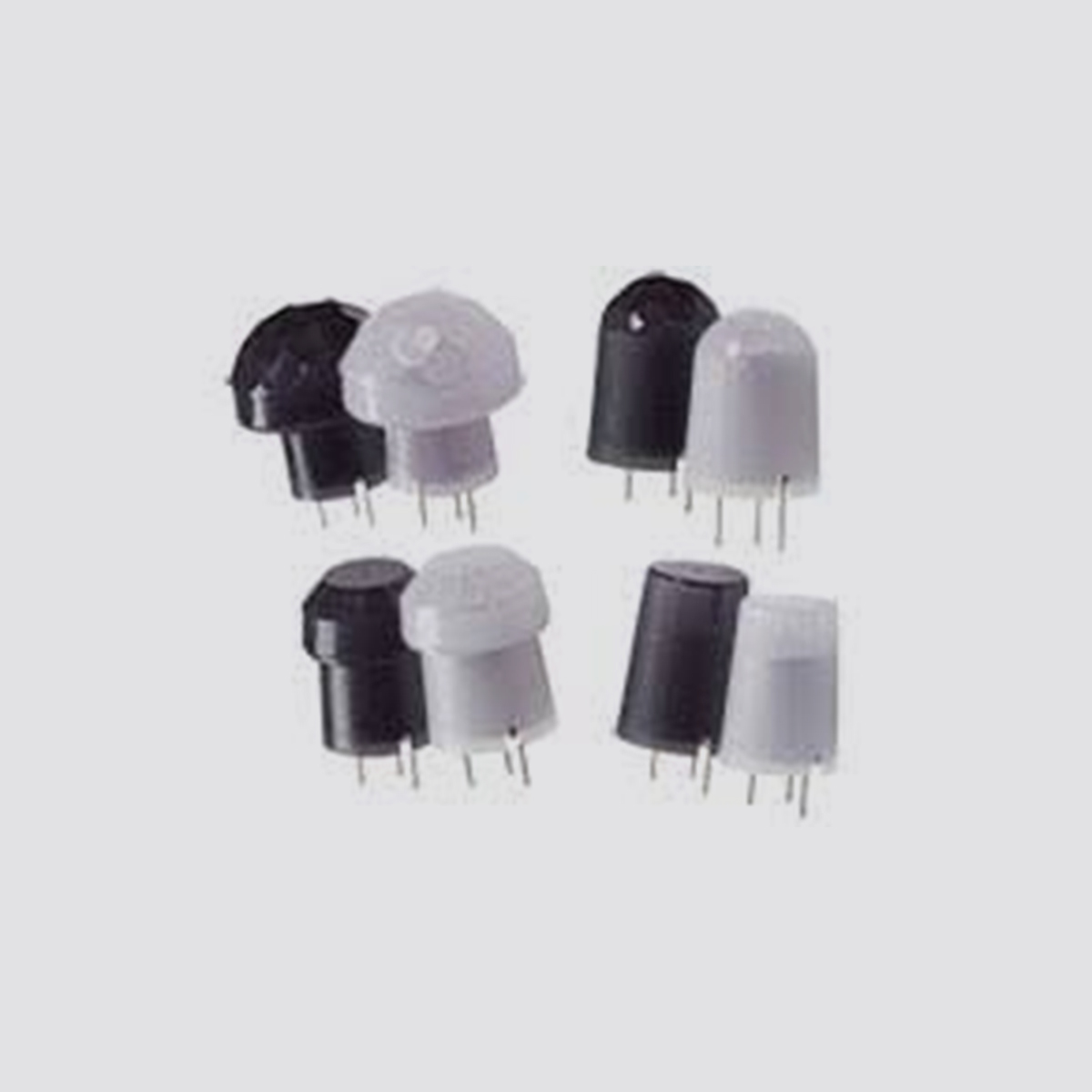
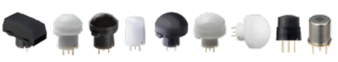
PaPIRs design features
The PIR motion sensors from Panasonic offer crucial advantages over conventional PIR motion sensors. The unique design concept (explained below) ranges from the production of the pyroelectric sensing devices to the internal signal processing, thus guaranteeing an optimal detection capability and high reliability
Technical information for all sensors (EKM and AMN)
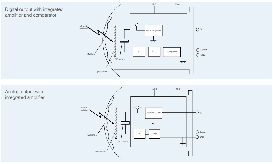
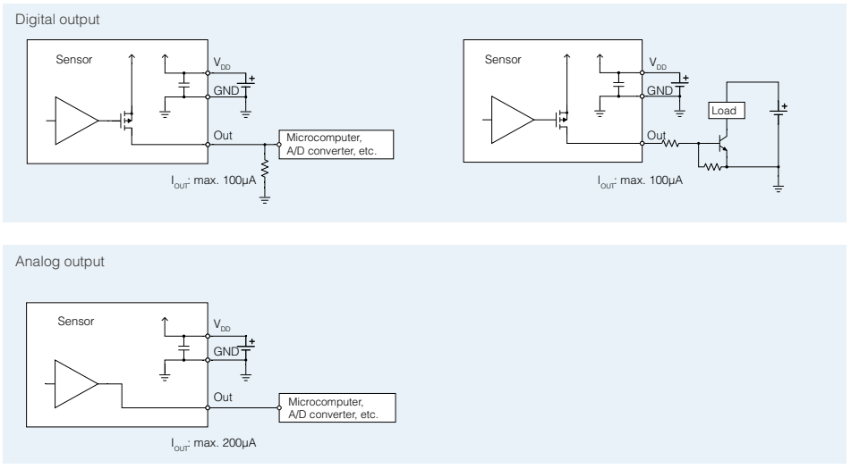
Block diagram output circuit
Wiring diagram
Notes:
Digital output types:
The output signal for the digital output type is from inside FET drain, therefore pull-down resistors are necessary. Please select an output resistor (pull-down concept) in accordance with VOUT so that the output current is maximum 100μA. If the output current is more than 100μA, this may cause false alarms.
If the microcomputer has a pull-down function, there is no need for a resistor as long as the output current does not exceed 100µA.
Analog output types (EKMC26 series):
In either case, a microcomputer or a resistor needs to be chosen in accordance to VOUT, so that the output current is maximum 200µA.
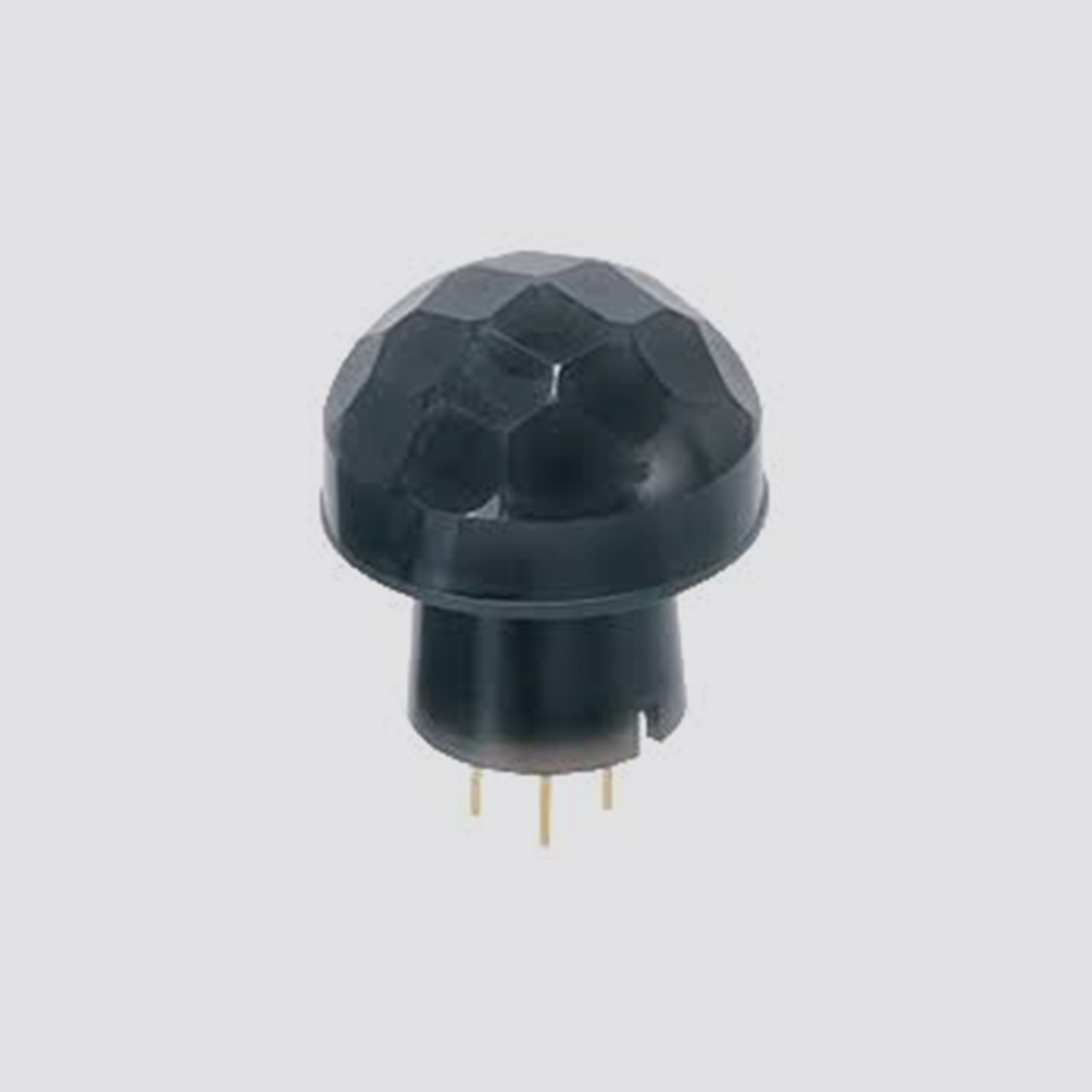
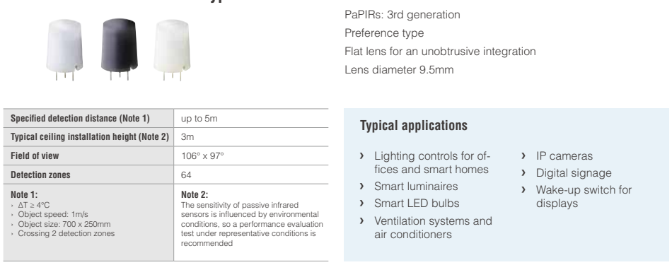
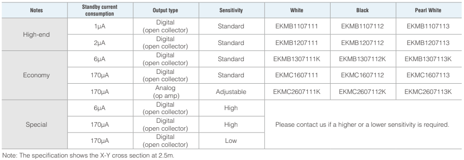
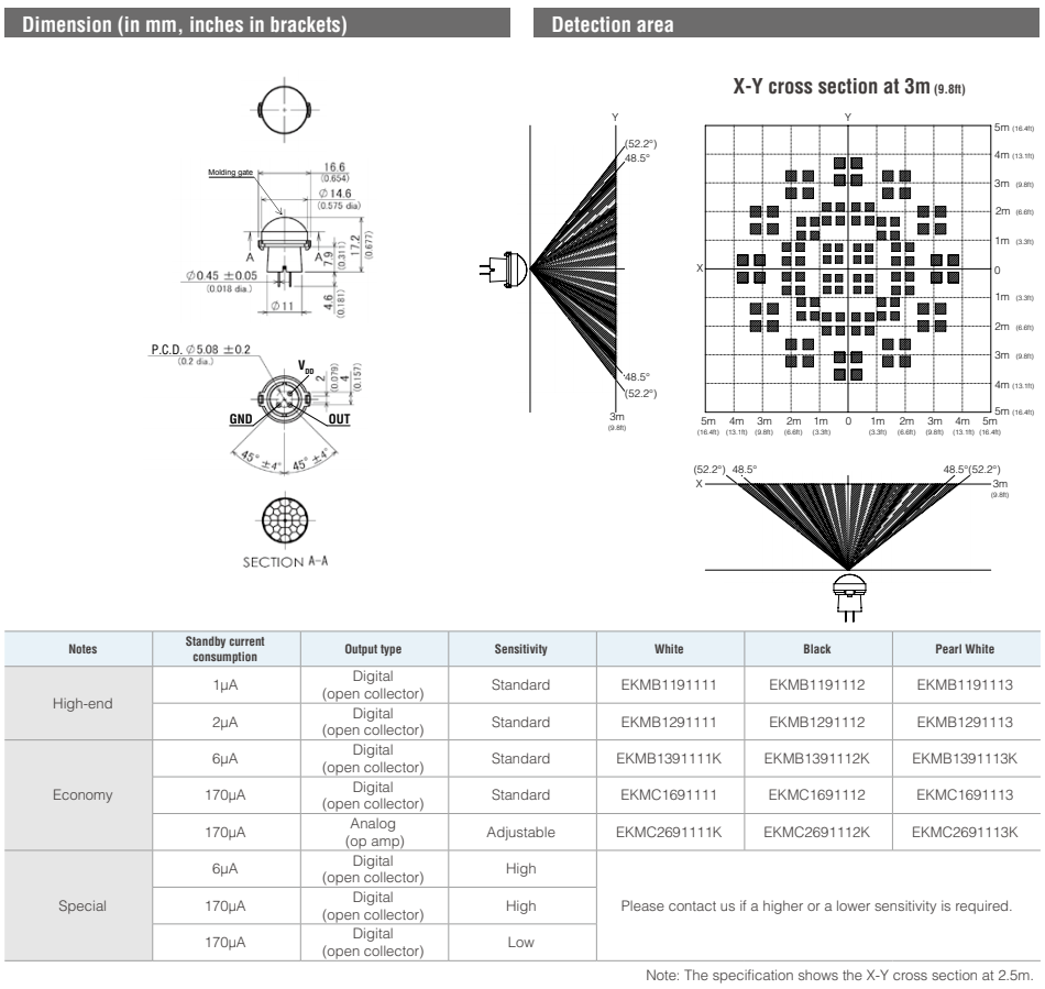
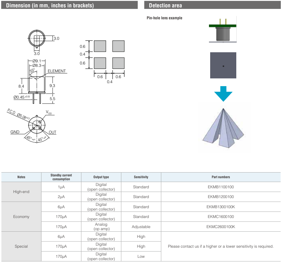
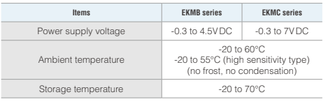
EKM - Standard Detection Type
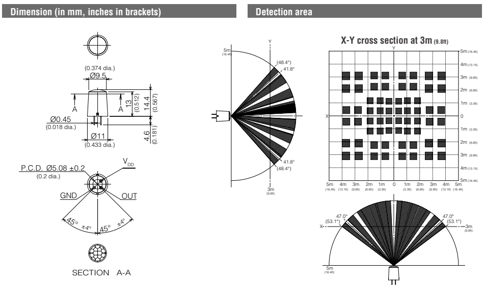
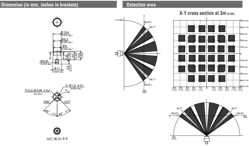
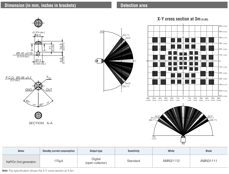
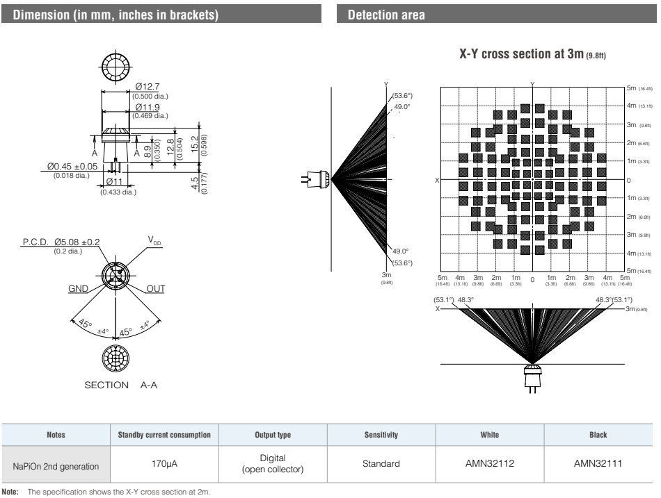
Note: The specification shows the X-Y cross section at 2.5m.
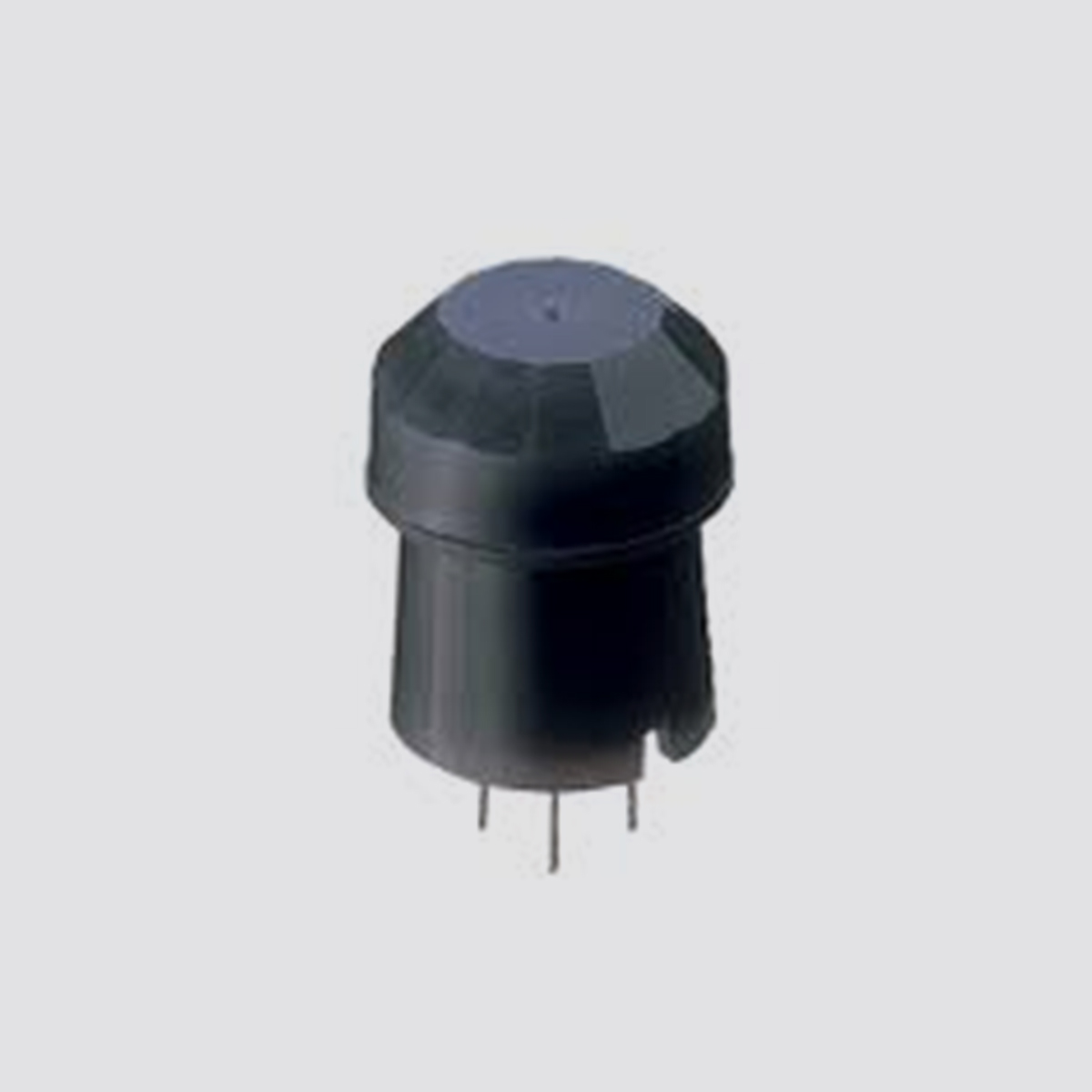
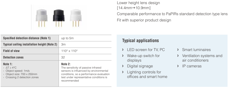
EKM - Low Profile Type
EKM - Slight Motion Detection Type
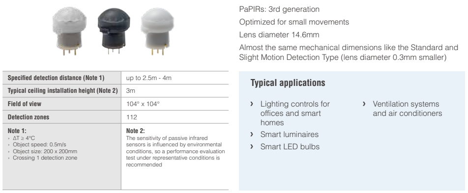
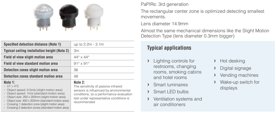
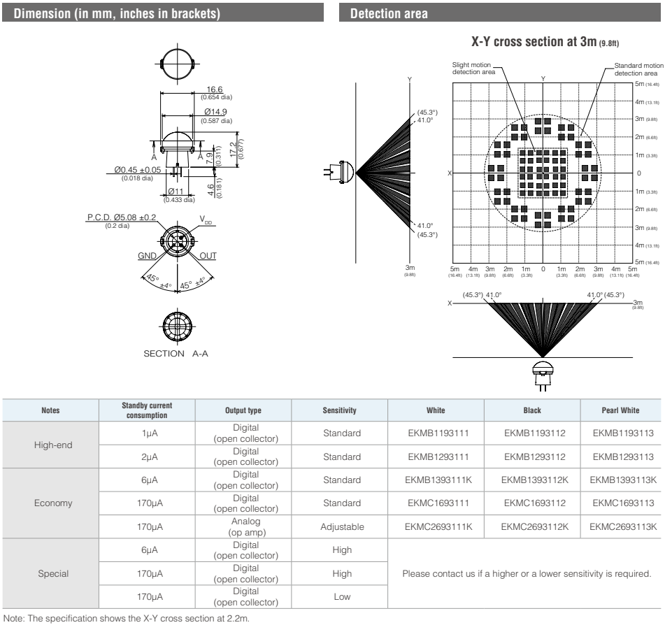
EKM - Standard and Slight Motion Detection Type
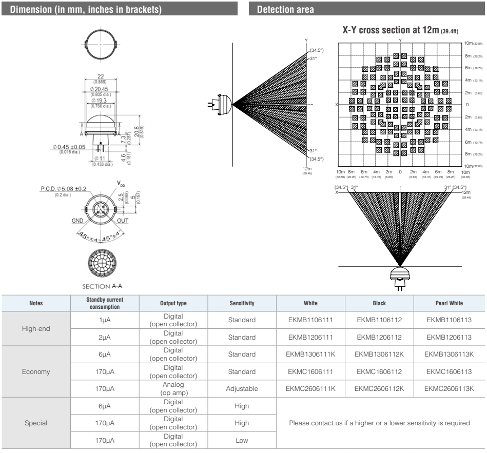
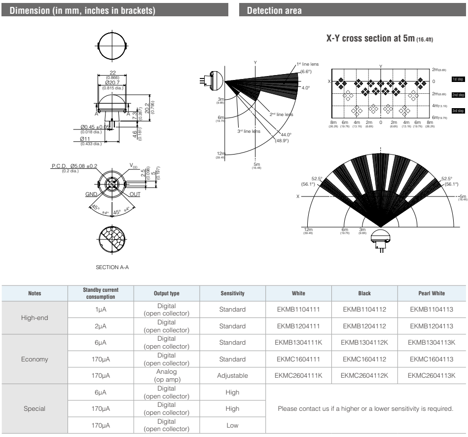
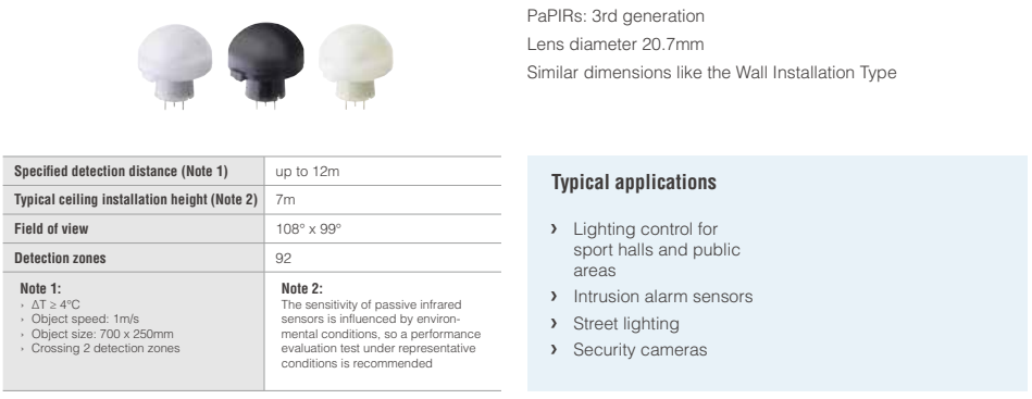
EKM - High Density Long Distance Detection Type
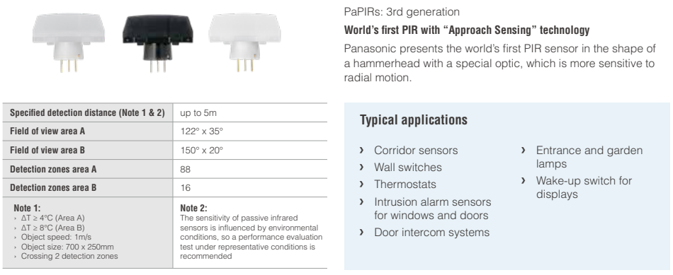
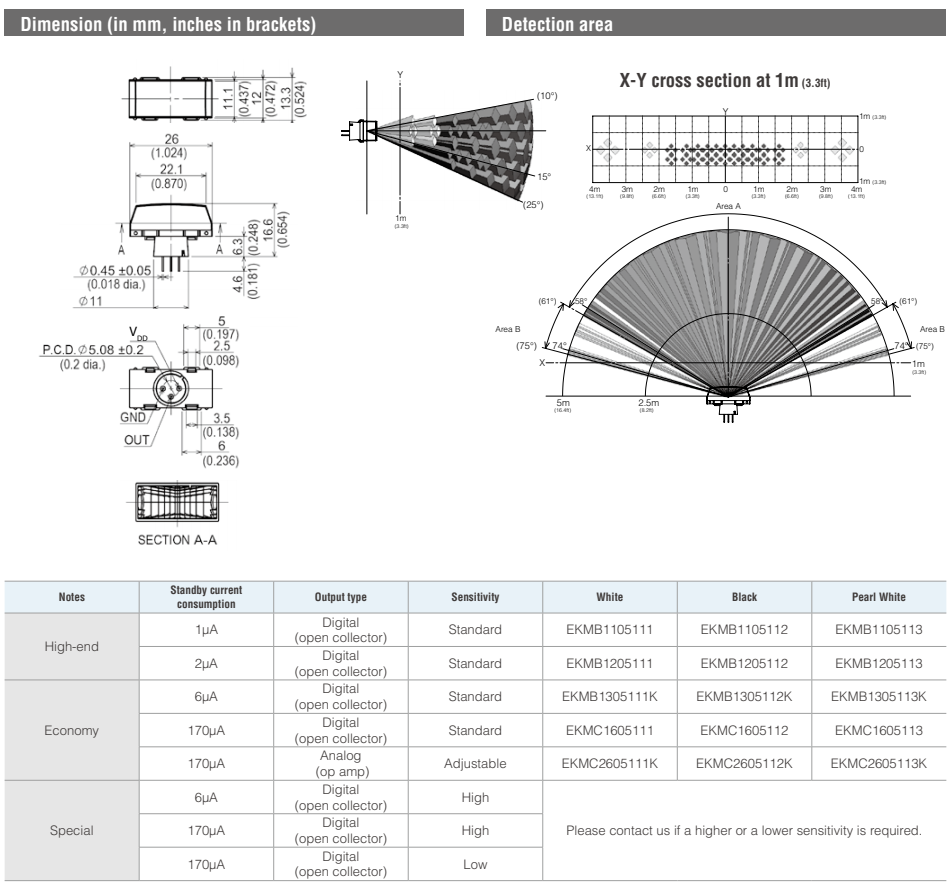
EKM - Horizontally Wide Detection Type
EKM - Wall Installation Detection Type (corner)
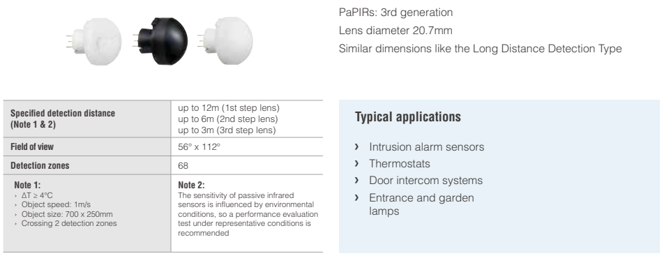
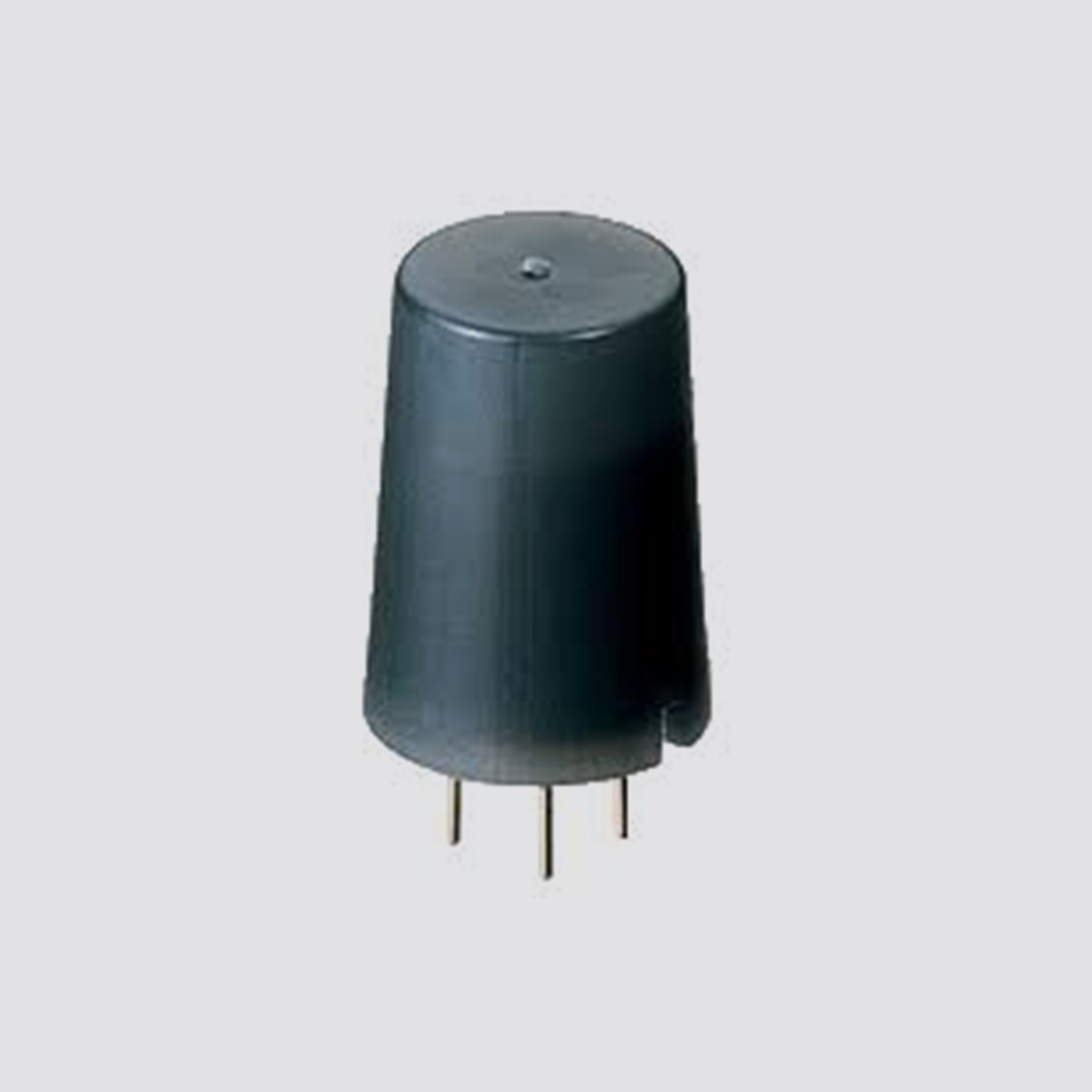
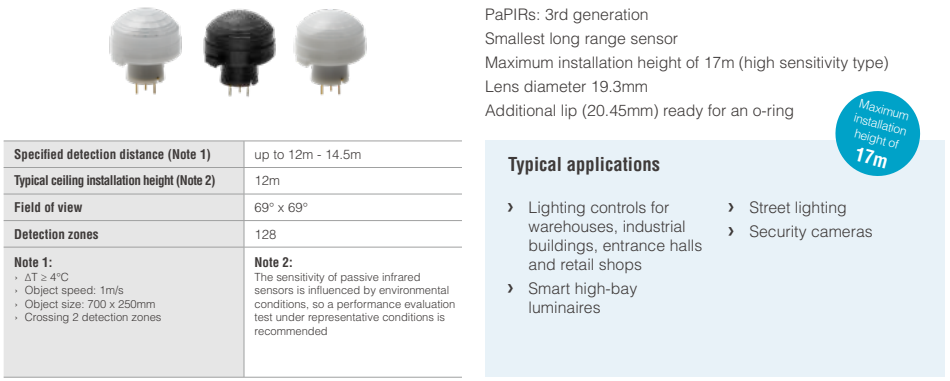
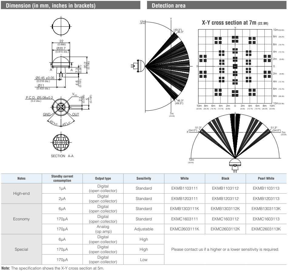
EKM - Long Distance Detection Type
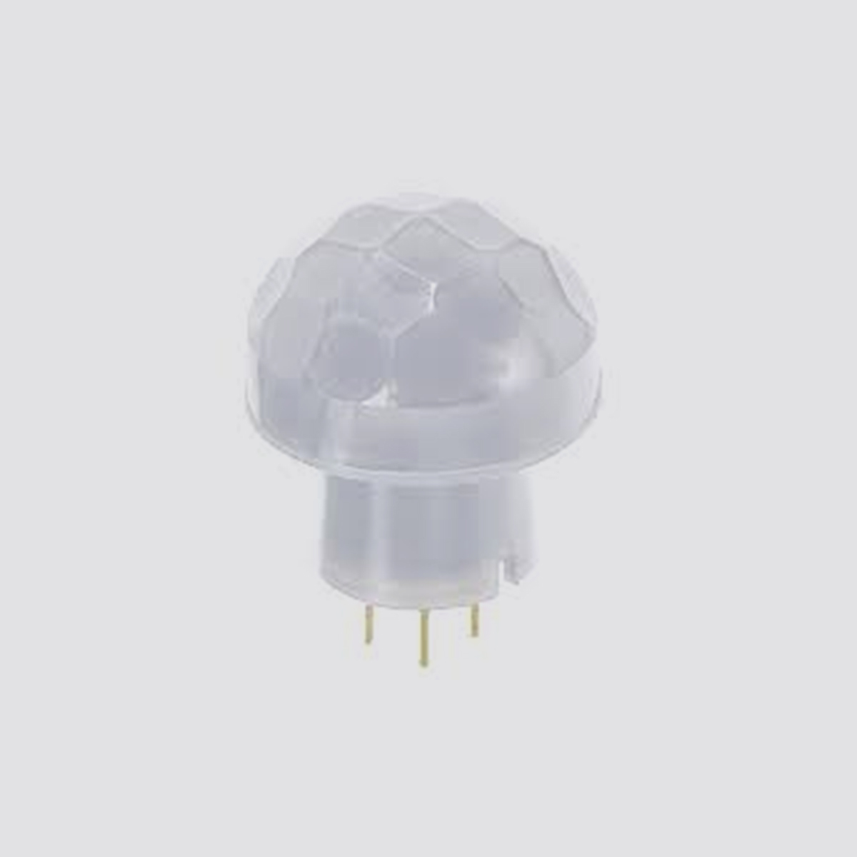
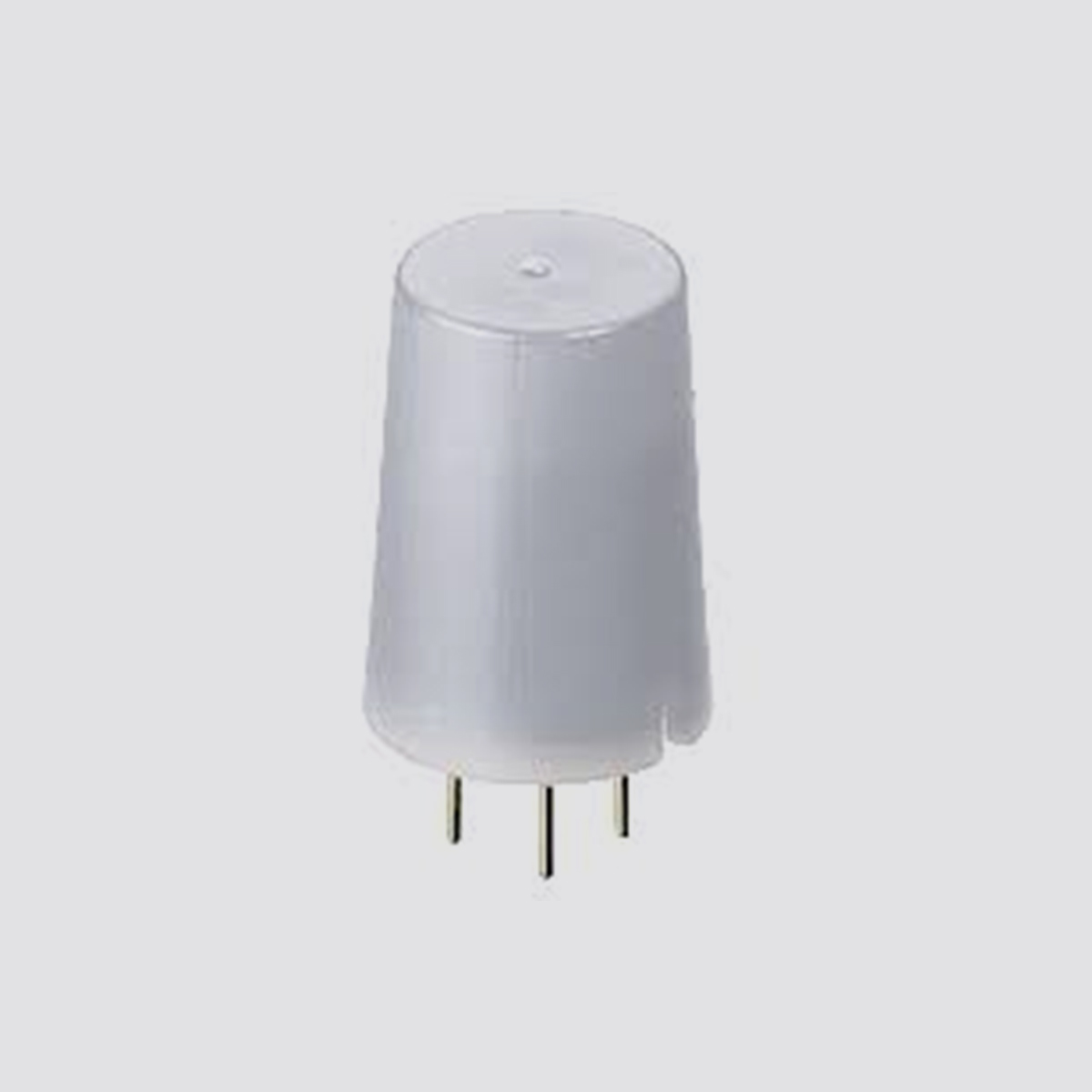
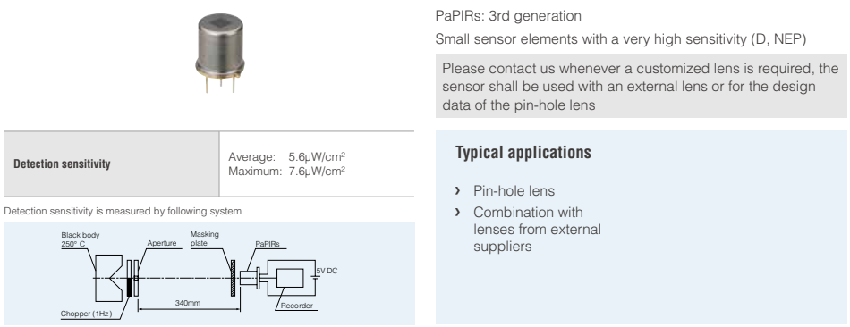
EKM - Lensless Type
EKM - Characteristics
EKM - Maximum rated values
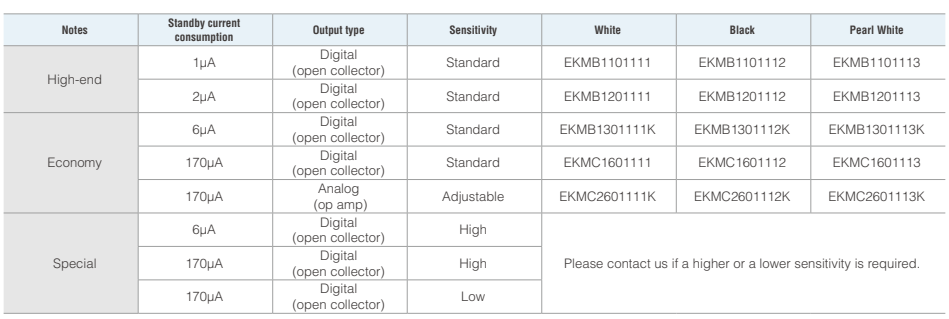
EKM - Electrical characteristics (digital output types)
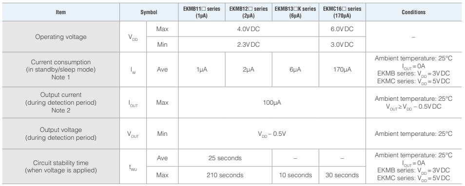
Note 1:
The total current consumption during detection is the current consumption in standby mode (IW) plus the output current (IOUT). For the 1μA type the average current consumption (IW) is 1μA in sleep mode and 1.9μA in standby mode. Please also refer to the timing charts on the next page.
Note 2:
Please select an output resistor (pull-down concept) in accordance with VOUT so that the output current is maximum 100μA.
EKM - Electrical characteristics (analog output)
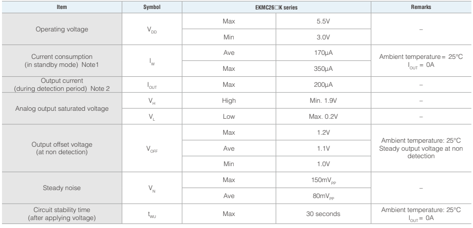
Note 1:
The total current consumption during detection is the current consumption in standby mode (IW) plus the output current (IOUT).
Note 2:
The output offset voltage has a certain tolerance. Please assure to measure the offset voltage before setting the upper and lower threshold values.
Otherwise the threshold window could be unsymmetrical relative to the offset voltage.
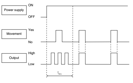
Timing chart
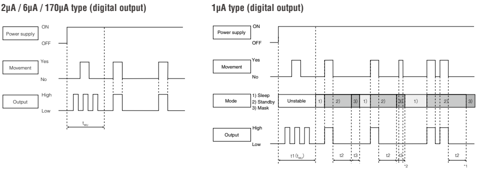
Explanation of the timing
tWU :Circuit stability time: about 25 seconds (typ.) for 2μA type, max.10 seconds for 6μA type, max. 30 seconds for 170μA type.While the circuitry is stabilizing after the power is turned on, the sensor output is not fixed in the High or Low state. This is true regardless of whether or not the sensor has detected anything.
Explanation of modes
1) Sleep mode: When the output is Low. The electrical current consumption is around 1μA
2) Standby mode: After the sensor's output has reached High status, the sensor switches to standby mode. The electrical current consumption gets close to
1.9μA. When the sensor's output returns to its Low value after the "hold time" has expired, the sensor switches again to sleep mode.
3) Mask mode: Time during which the output is forced to Low status after the end of the standby mode. (No detection is possible during this period.)
Explanation of the timing
t1) (tWU) : Circuit stability time: about 25 seconds (typ.) While the circuitry is stabilizing after the power is turned on, the sensor output is not fixed in the High or Low state. This is true regardless of whether or not the sensor has detected anything.
t2) Standby hold time: About 2.6 seconds (typ.) after the last detection of a signal. (*1)
t3) Mask time: About 1.3 seconds (typ.) During this stage, even if the sensor detects something, the output will not switch to High. (*2)
170μA type (analog output)
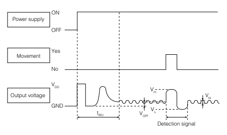
Explanation of the timing
tWU: Circuit stability time: max. 30 seconds While the circuitry is stabilizing after the power is turned on, the sensor output is not fixed. This is true regardless of whether or not the sensor has detected anything.
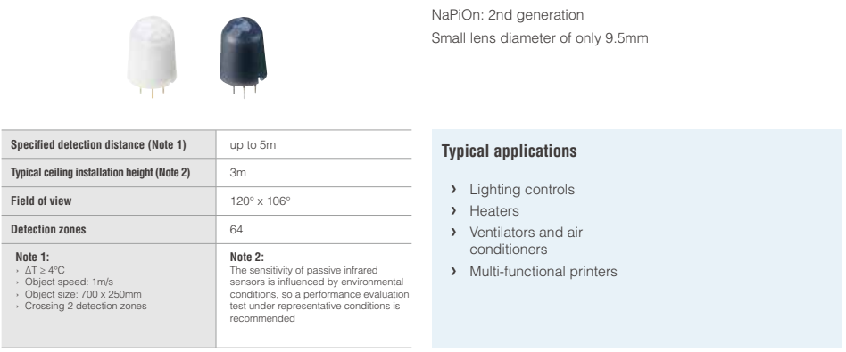
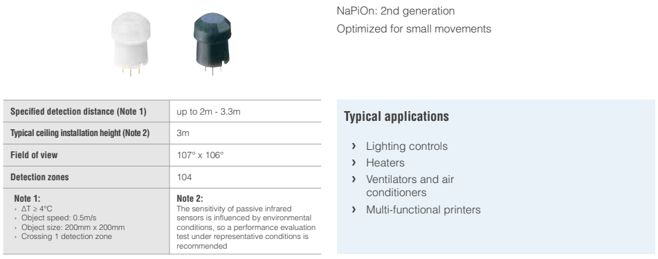
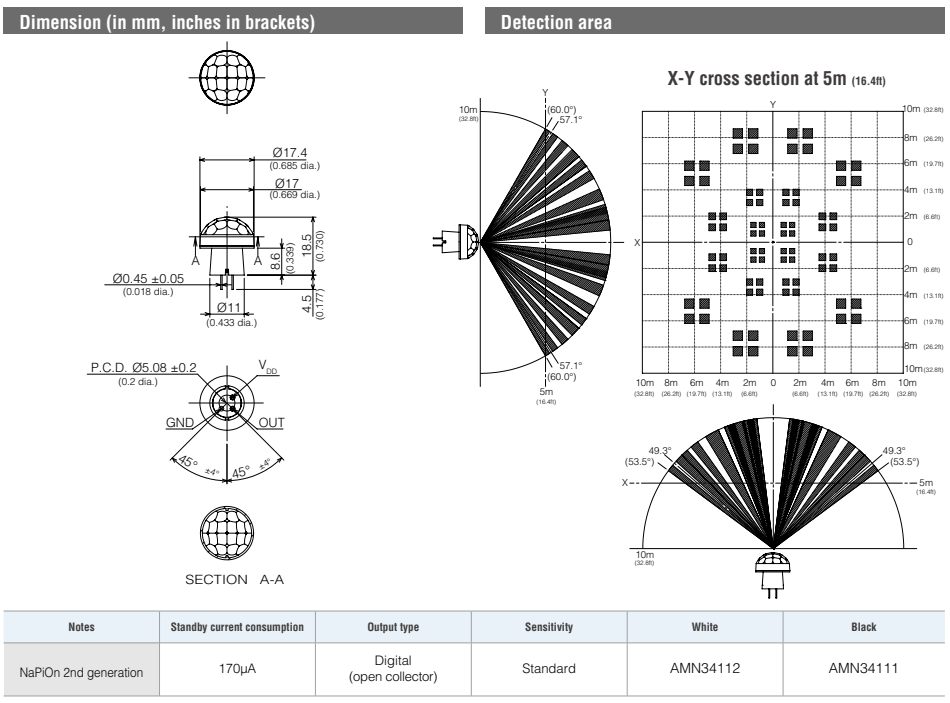
AMN - Standard Detection Type
AMN - Slight Motion Detection Type
AMN - Spot Detection Type
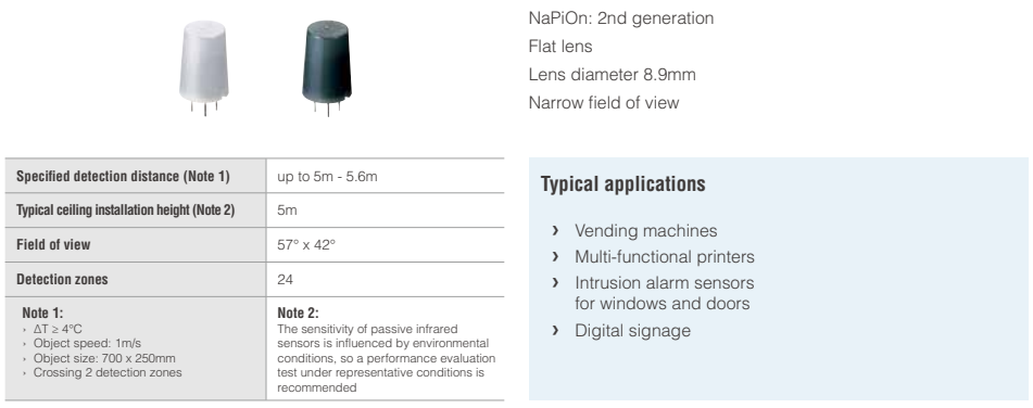
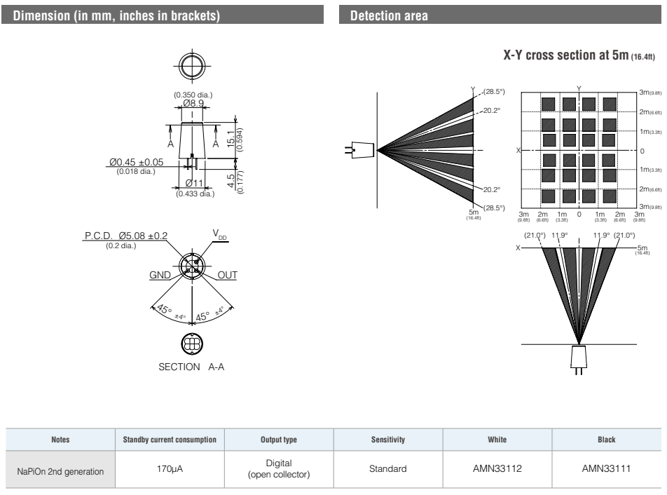
AMN - 10m Detection Type (long distance)
AMN - Characteristics
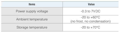
AMN - Maximum rated values (digital output)
AMN - Electrical characteristics (digital output)
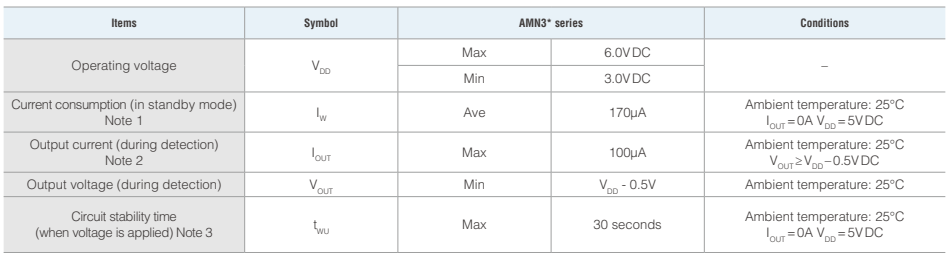
Note 1: The total current consumption is equal to the current consumption in standby mode (IW) plus the output current (IOUT).
Note 2: Please select an output resistor (pull-down concept) in accordance with VOUT so that the output current is maximum 100μA. If the output current is more than 100μA, this may cause false alarms.
Note 3: The sensor temperature has to be constant for the time specified.
Digital output
Explanation of the timing
tWU: Circuit stability time: max. 30 seconds
While the circuitry is stabilizing after the power is turned on, the sensor output is not fixed in the High or Low state. This is true regardless of whether or not the sensor has detected anything.
Cautions for use
Basic principles
PaPIRs are pyroelectric infrared sensors that detect variations in infrared rays.
However, detection may not be successful in the following cases: lack of movement or no temperature change in the heat source. They could also detect the presence of heat sources other than a human body. Efficiency and reliability of the system may vary depending on the actual operating conditions:
1) Detecting heat sources other than the human body, such as:
a) small animals entering the detection area
b) When a heat source, for example sun light, incandescent lamp, car headlights etc., or strong light beam hit the sensor regardless whether the detection area is inside or outside.
c) Sudden temperature change inside or around the detection area caused by hot or cold wind from HVAC, or vapor from a humidifier, etc.
2) Difficulty in sensing the heat source
a) Glass, acrylic or similar materials standing between the target and the sensor may not allow a correct transmission of infrared rays.
b) Non-movement or quick movements of the heat source inside the detection area.
(Please refer to the table on page 8 or 11 for details about movement speed.)
3) Expansion of the detection area
In case of a considerable difference in the ambient temperature and the human body temperature, the detection area may be larger than the configured detection area.
4) Malfunction / Detection error
On rare occasions, an erroneous detection signal may be output due to the nature of pyroelectric element. When the application cannot tolerate erroneous detection signals, take countermeasures by introducing a pulse-count circuit, etc.
5) Detection distance
Panasonic's PIR Motion sensors state the detection distance in the specifications because they are usually provided with the lens (please refer to item 6 for lensless types). The PIR Motion sensor could detect variations in infrared rays however such variations are decided by following three factors.
• The temperature difference between the target and the surroundings:
The larger the temperature difference, the easier it is to detect targets.
• Movement speed: If the target is moving at a slower or faster speed than specified in the tables, the detection ability may be lower.
• Target size: The human body is the standard. If the target is smaller or larger than specified in the table, the detection ability may be lower.
The detection distance explained in our data sheet is defined by the three factors mentioned above. Panasonic's standard for the temperature difference between the target and the surrounding is defined as 4°C. The larger the temperature difference, the longer the detection distance. If the temperature difference is 8°C, which is twice as much as the standard, the detection distance will be approx. 1.4 times longer than the distance at 4°C. For example, if targets at a distance of 5m can be detected at 4°C, then the sensor can detect targets at a distance of 7m at 8°C. (This is based on the theory that the detection sensitivity will vary inversely with the square of the distance.)
6) Lensless Type
The lensless type cannot detect any targets because it is not possible to focus infrared variations into the sensor chip. It is not possible to determine the detection distance and the field of view without a lens. Please provide your own lens based on your lens design concept.
7) Lens material and the plate setting in front of the lens
Typically, the only material that can be passed by infrared rays is Polyethylene.
(The lens material of Panasonic's PIR Motion sensors is "High density polyethylene, HDPE".) When you need to set a plate in front of the lens, please choose one made from the Polyethylene. Please note the thickness or color of the plate will affect the detection ability, e.g. it may make the detection distance shorter. Therefore, please confirm by testing the sensor with the plate under realistic conditions.
Cautions
1) Refer to the newest specification regarding optimal operating environment conditions.
2) Do not solder with a soldering iron above 350°C (662°F) or for more than 3 seconds.
This sensor should be hand-soldered.
3) To maintain stability of the product, always mount it on a printed circuit board.
4) Do not use liquids to wash the sensor. If washing fluid gets into the lens, it can reduce the performance.
5) Do not use a sensor after it has fallen on the ground.
6) The sensor may be damaged by ±200 volts of static electricity.
Avoid direct hand contact with the pins and be very careful when operating the product.
7) When wiring the product, always use shielded cables and minimize the wiring length to prevent noise disturbances.
8) The inner circuit board can be destroyed by a voltage surge.
The use of surge absorption elements is highly recommended.
Surge resistance: below the power supply voltage value indicated in the section on maximum rated values.
9) Please use a stabilized power supply. Noise from the power supply can cause operating errors.
Noise resistance: max. ±20V (square waves with a width of 50ns or 1μs)
To reduce the effect of noise from the power supply , install a capacitor on the sensor's power supply pin.
10) Operation errors can be caused by noise from static electricity, lightnings, cell phones, amateur radio, broadcasting offices, etc
11) The detection performance can be reduced by dirt on the lens, please be careful.
12) The lens is made of soft materials (Polyethylene).
Please avoid adding weight or impacts that may change its shape, causing operation errors or reduced performance.
13) The specified temperature and humidity levels are suggested to prolong usage. However, they do not guarantee durability or environmental resistance.
Generally, high temperatures or high humidity levels will accelerate the deterioration of electrical components. Please consider both the planned usage and environment to determine the expected reliability and length of life of the product.
14) Do not attempt to clean this product with detergents or solvents such as benzene or alcohol, as these can cause shape or color alterations.
15) Avoid storage in high, low temperature or liquid environments.
Also, avoid storage in environments containing corrosive gas, dust, salty air etc.
Adverse conditions may cause performance deterioration and the sensor's main part or the metallic connectors could be damaged.
16) Storage conditions
Temperature: +5 to +40°C, humidity: 30 to 75%
Please use within 1 year after delivery.
Safety precautions
Obey the following precautions to prevent injury or accidents.
1) Do not use these sensors under any circumstance in which the range of their ratings, environment conditions or other specifications are exceeded. Using the sensors in any way which causes their specifications to be exceeded may generate abnormally high levels of heat, emit smoke, etc., resulting in damage to the circuitry and possibly causing an accident.
2) Our company is committed to making products of the highest quality and reliability. Nevertheless, all electrical components are subject to natural deterioration, and durability of a product will depend on the operating environment and conditions of use. Continued use after such deterioration could lead to overheating, smoke or fire. Always use the product in conjunction with proper fire-prevention, safety and maintenance measures to avoid accidents, reduction in product life expectancy or break-down.
3) Before connecting, check the pin layout by referring to the connector wiring diagram, specifications diagram, etc., to verify that the connector is connected properly. Mistakes made in connection may cause unforeseen problems in operation, generate abnormally high levels of heat, emit smoke, etc., resulting in damage to the circuitry.
4) Do not use any motion sensor which has been disassembled or remodeled.
5) Failure modes of sensors include short-circuiting, open-circuiting and temperature rises. If this sensor is to be used in equipment where safety is a prime consideration, examine the possible effects of these failures on the equipment concerned, and ensure safety by providing protection circuits or protection devices.
Example : Safety equipment and devices, traffic signals, burglar and disaster prevention devices, controlling and safety device for trains and motor vehicles
 +86-0755-29898410 +86-0755-29898460
  ron@xaori.net